Prior to work activities commencing on any project regardless of scope, the presence of asbestos containing materials must be established and risk managed – refer Asbestos Management Procedure and Policy. At SHAPE asbestos is assumed to be present in all materials until proven otherwise.
During the project’s pre-construction phase the building asbestos register (which may be referred to as a “Division 5” report in Victoria) is requested from the building manager for review as part of the development of the project Risk Register and Project Delivery Plan.
Note: the building’s asbestos register / report or “Div 5” report is often insufficient for demolition and refurbishment activities, unless the report includes destructive sampling and testing of all locations included in the project’s scope of works (including voids, risers, bulkheads, etc.)
Buildings constructed prior to 31 December 2003 are always assumed to contain asbestos until proven otherwise. Unless there is absolute certainty the building and or work areas do not contain asbestos, a hygienist must be engaged to conduct further invasive inspections and sampling prior to work commencing (in Victoria, a hazardous material report sufficient for demolition and refurbishment activities is referred to as a “Division 6” report).
NB existing building hazardous materials registers and clearance certificates should not be relied upon as a sole source of information to determine absolute certainty asbestos is not present.
Buildings constructed after 31 December 2003 are still assumed to contain asbestos unless the building owner or manager can provide one of the following:
- Asbestos register confirming no Asbestos is present in the entire scope of works
- A hygienist certificate confirming no asbestos is present
- A written statement confirming no asbestos is present
In the ACT only: all workers must have completed at least one “Asbestos Awareness” course through a Registered Training Organisation (RTO):
- 11804NAT
- 10675NAT
- 10314NAT
- CPCCDE3014A
- CPCCDE3015A
- CPCCBC4051A
- CPCCBC5014A
In addition, all mechanical, refrigeration, electrical, cabling, telecommunications and plumbing trades must have also completed “Working Safely with Asbestos Containing Materials 10852NAT”.
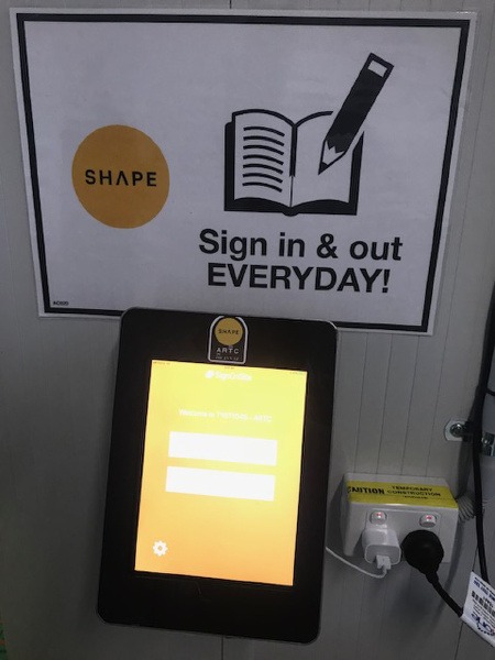
Evidence of this training must be sighted by the SHAPE Representative and documented on the worker’s Site Induction Record.
Where asbestos is present or assumed to be present:
The project Project Delivery Plan and project Risk Register detail the project specific asbestos hazards and controls, including controls for asbestos removal works if part of the project scope.
The project manager has provided a copy of the building asbestos register to all trade contractors as part of the subcontract documentation.
The Site Induction details all known locations of asbestos containing materials and other site specific controls for treating all materials as suspect until proven otherwise.
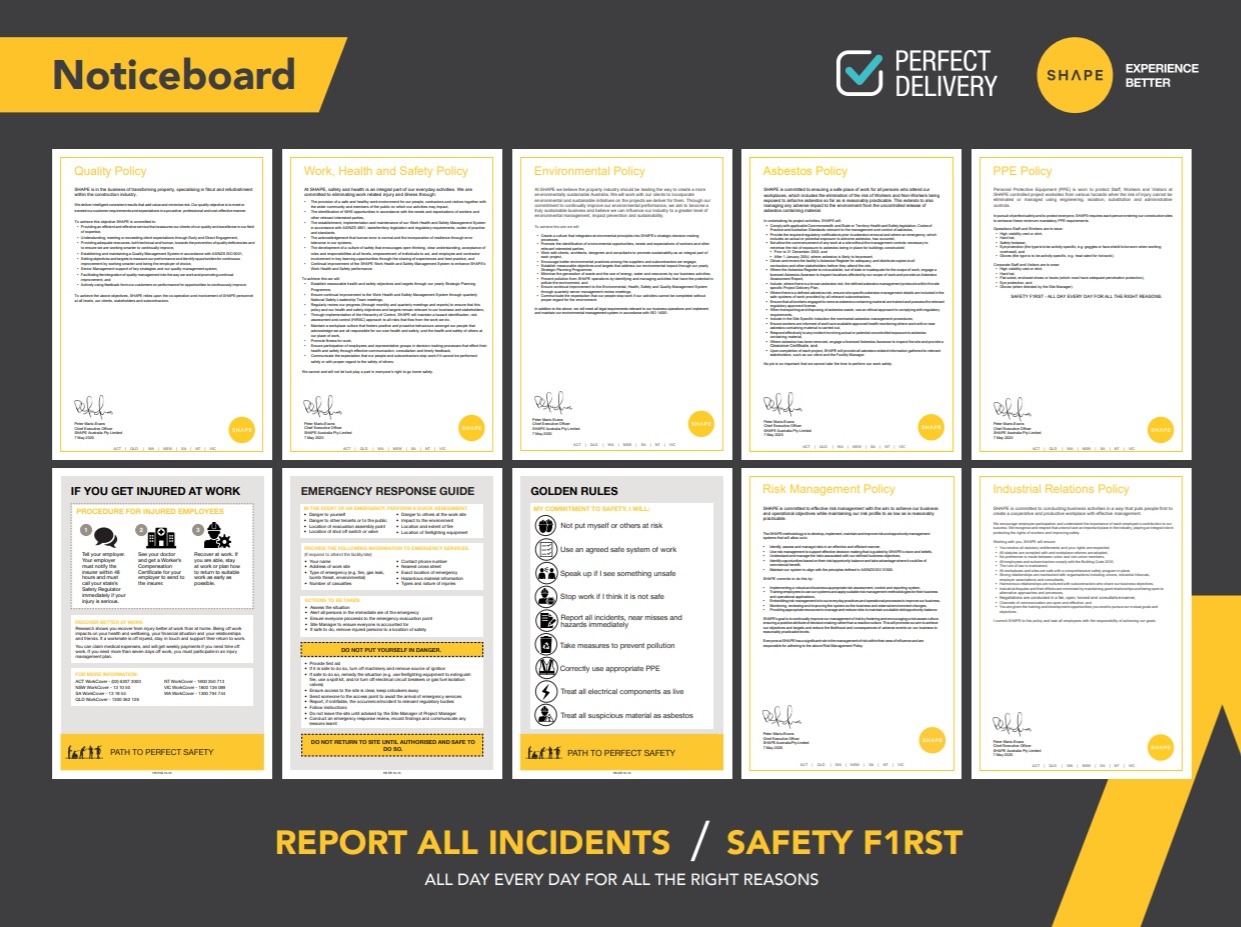
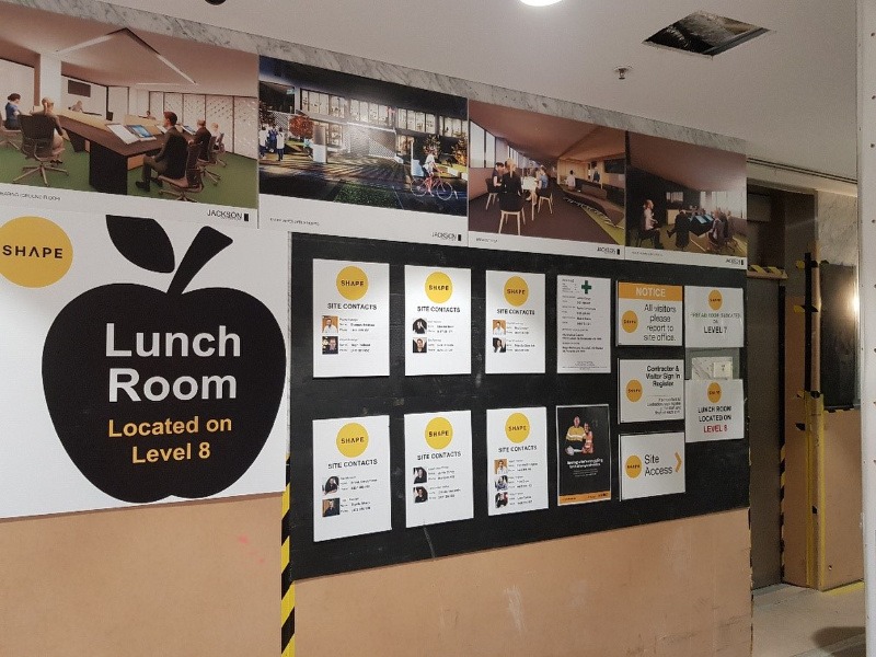
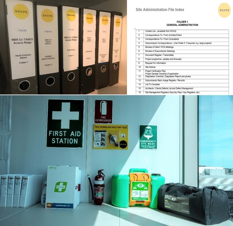
The building asbestos register is posted at the site noticeboard so that all workers have access to it.
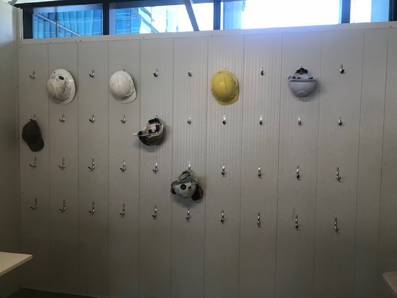
All known and or assumed asbestos containing material is labelled or signposted where reasonably practical to do so.
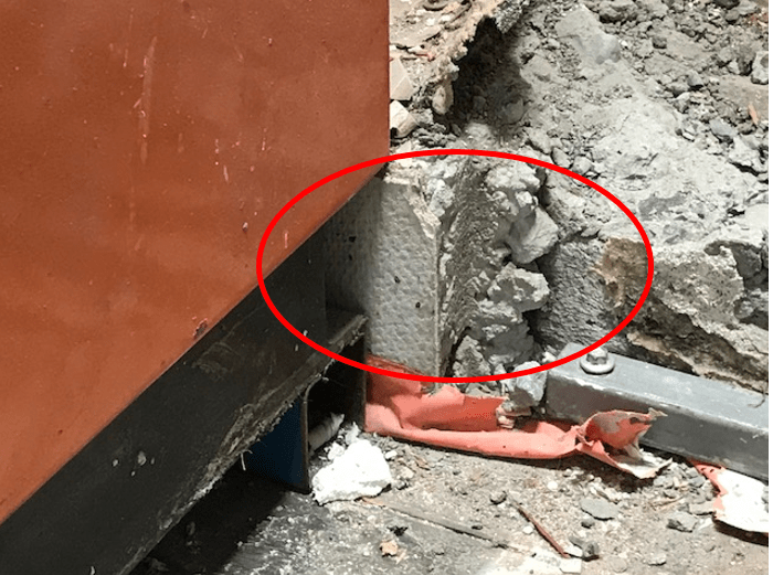
All closed ceilings, voids, bulkheads, service risers and building materials are presumed to contain asbestos until a hygienist has confirmed otherwise.
Consideration is given to the potential introduction of asbestos-contaminated soils, fill and mulch products (which are often man-made products constructed from recycled or waste material).
Soil, fill and mulch products are only procured from reputable suppliers, the materials are visually inspected upon delivery for any signs of visible contamination, and if in doubt project teams will consult with an Occupational Hygienist to determine a suitable and site-specific inspection and sampling process.
Note: for schools and public infrastructure projects, always seek proportionate sampling and testing processes from an Occupational Hygienist as the material arrives to site.
All sites that contain or are suspected to contain asbestos will complete and display SHAPE’s Unexpected ACM Discovery or Exposure Flowchart. This flowchart serves as the project’s asbestos exposure emergency response plan on the site notice board. Note: The flowchart must be filled in to identify a worker decontamination area in consultation with building management, such as an existing shower or change facility. This response plan is also reflected in the Project Project Delivery Plan and project Risk Register.
Contractor SWMS detail asbestos related hazards and controls where there is a risk of asbestos disturbance through work activities.
Removal work is to be engaged only by an appropriately licenced contractor.
Removal work will require an asbestos removal plan and formal notification to the regulator.
Air monitoring kept on file for all asbestos removal activities regardless of the type of material, i.e. bonded or friable.
Hazardous waste is tracked through the Waste Management Register or through the site diary – waste transport and receipt dockets are filed.
ACM transport vehicles have the appropriate licenses or authorities – copies of records are maintained on site.
Workers are regularly consulted regarding any changed circumstances in relation to asbestos containing materials, i.e. removal works, unexpected discoveries, air monitoring outcomes, sampling outcomes, suspected exposure incidents.
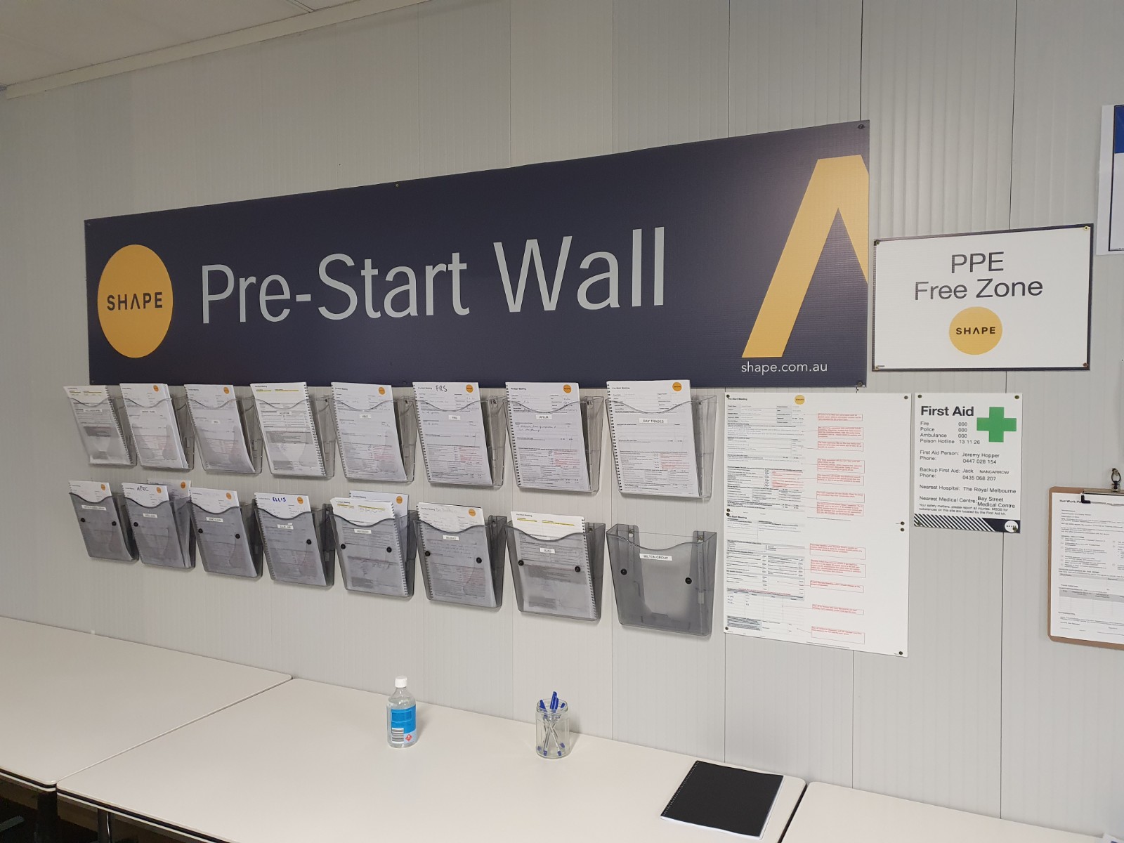
Communication should be delivered through Pre Start Meetings, Toolbox Talks and the Site Induction.
Building management consulted regarding asbestos related matters such as removal works, unexpected discoveries, air monitoring outcomes, sampling outcomes, suspected exposure incidents.
All unexpected discoveries are to be reported as High Risk Near Miss incidents regardless of the outcome – i.e. a suspected discovery that is later proven not to be asbestos through testing is still to be reported.
Concrete pumping is defined by legislation as a high risk activity and requires detailed planning and coordination prior to commencing. Where boom pumps are to be used, review of the Lifting Operations SHAPE Minimum Standard and the Plant and Equipment SHAPE Minimum Standard will provide additional guidance.
During pre-construction, the project team reviews the scope of works with respect to concrete pumping activities for inclusion into the project Risk Register and Project Delivery Plan.
Contractor Safe Work Method Statements (SWMS) are prepared by subcontractors for construction work associated with concrete pumping, and reviewed using the SWMS Review.
Relevant information, training, and instructions have been provided to workers who are involved in the activity. For example: Site Induction, Toolbox Talks, training in SWMS, Pre-Start Meetings, etc.
A Plant and Equipment Induction been completed, and the concrete pump has been entered into the site Plant and Equipment Register.
The concrete pump company has provided records of pump registration, pipe x-ray results, completion of daily logs, maintenance and service prior to arriving to site.
Worker competencies have been verified and copies taken as evidence.
Note: a boom pump requires the operator to have a high risk licence.
Risk Assessments consider and include:
- Weather conditions
- Site accessibility
- Site limitations
- Back up equipment
- Volume of concrete, i.e. number of trucks, timing between loads, etc.
- The designated pump washout area complies with environmental and local authority requirements
- A safe place has been identified where to clean the line
- Restricted work times (local council rules)
- Equipment capacity
- Concrete pump capacity
- Concrete supplier’s requirements
- Overhead power or other services
- Underground services, pits, etc.
The suitability of the pump location has been assessed with respect to access, other work activities, the public, and the shortest run of pump line.
Access routes for the pump and agitators have sufficient bearing capacity.
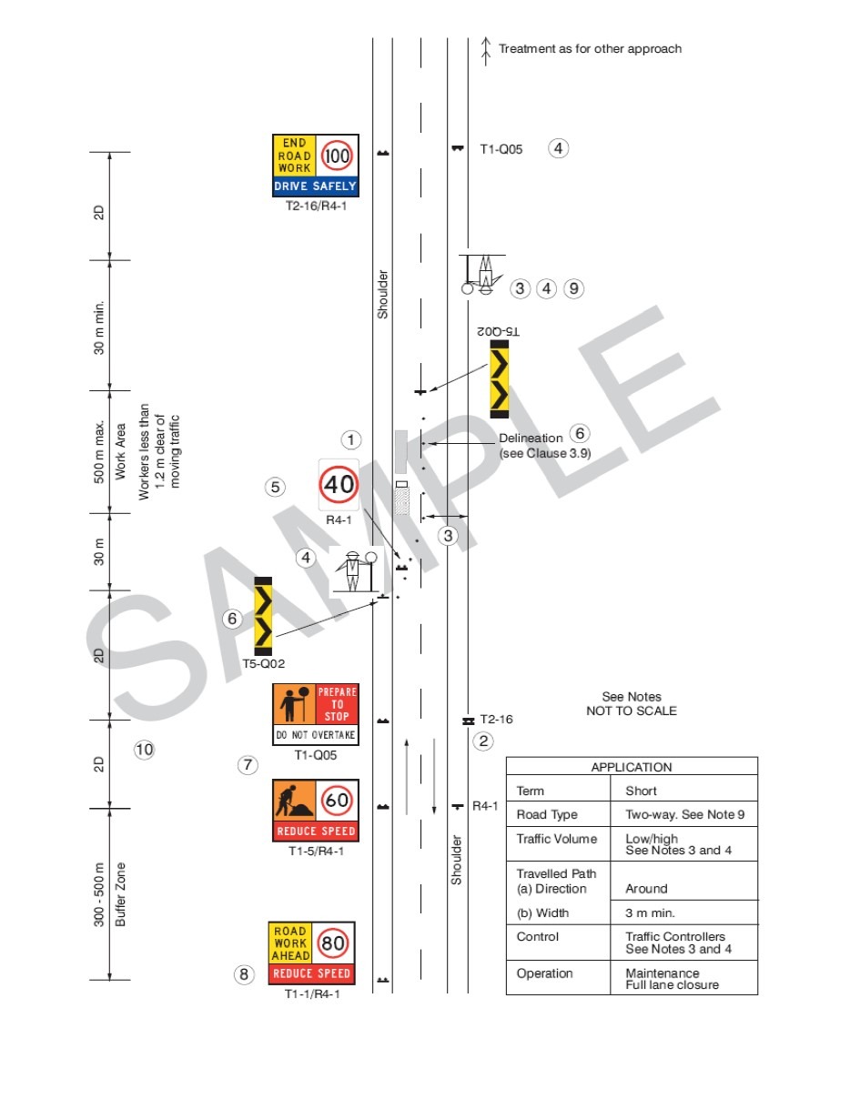
Access is provided for the general public, to public areas in the vicinity of the pumping unit and the delivery trucks, if the pump unit is set up in the street.
Note: Permits and the traffic management plan, including signage and exclusion zones, are reviewed and kept on site.
Scheduling of the pumping activities considers the full scope of the concrete works, to ensure adequate daylight hours to complete the task. Where operation of the plant is required at night, or in low light conditions, artificial lighting should be provided.
Clear access to the pump unit has been provided for concrete trucks.
Delivery pipes are positioned away from access ways, or exclusion zones have been implemented.
Steel pipes are secured to prevent movement and blow outs.
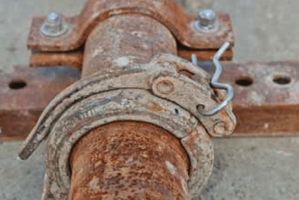
Pipe joining clamps have safety pins to ensure the clamp does not inadvertently open.
All lines, pipes, couplings and fittings must be capable of withstanding the maximum pump pressure (including blockages) or the pump pressure must be adjusted so that it does not exceed the pipeline rating.
A safe location has been identified and implemented for the concrete tester vehicle.
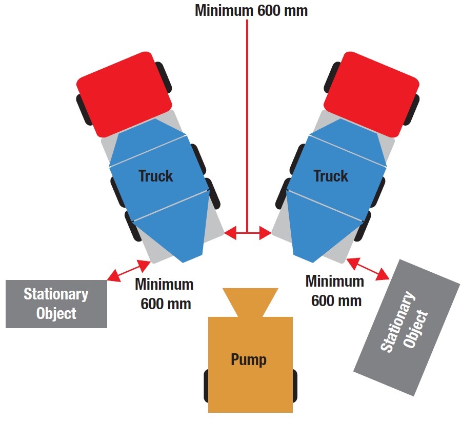
Concrete trucks have been suitably spaced between loads to prevent truck banking, traffic congestion and concrete perish.
Task Inspections are completed during pumping activities to ensure compliance to the approved work methods.
The agreed method of communication is in use and effective, e.g. two way radio, hand signals, whistle tones.
For Boom Pumps:
Factors have been considered that could affect the ability of the ground to provide adequate support (e.g. underground services, trenches, excavations, pits, tanks).
Where hazards have been identified, certification has been provided by a competent person that the surface has adequate bearing capacity to support the concrete pump (e.g. structural engineer, geotech engineer, scanning techniques).
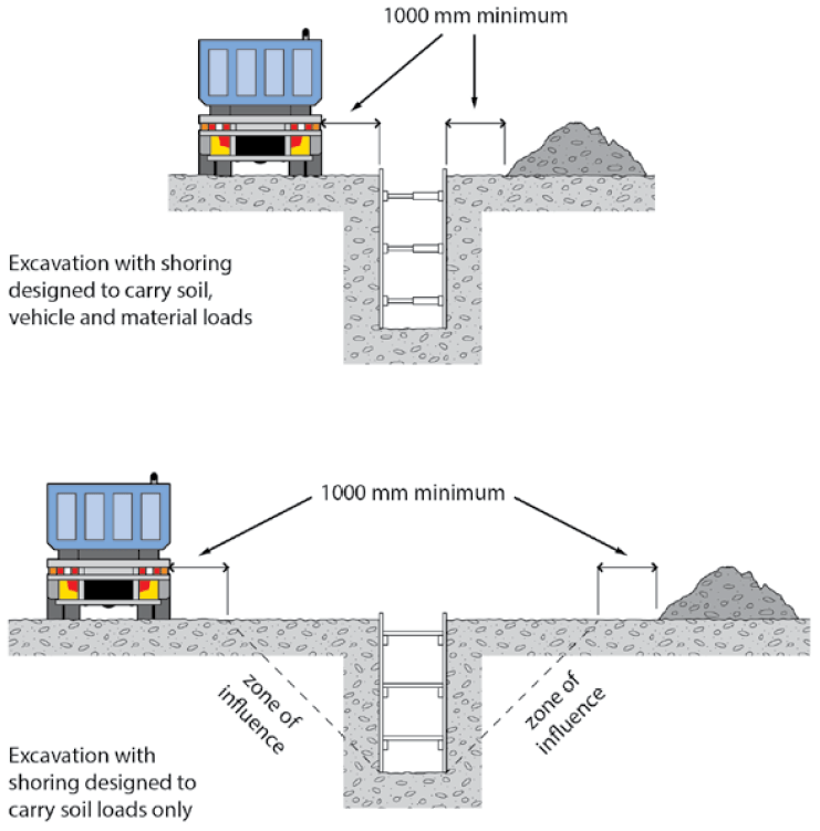
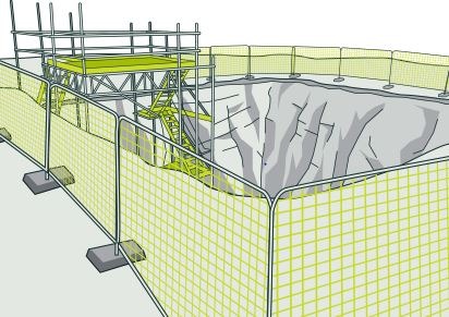
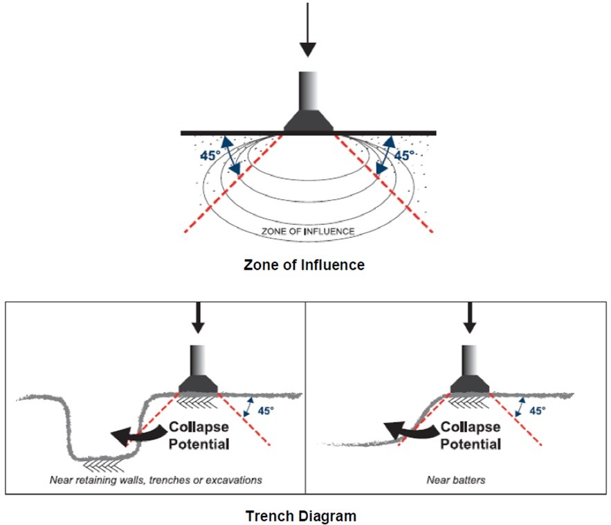
When a pump is positioned near a trench, the nearest outrigger to the trench must be at least as far away from the trench, as the trench is deep. This rule assumes a zone of influence working at a 45° angle.
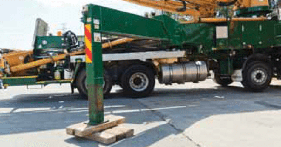
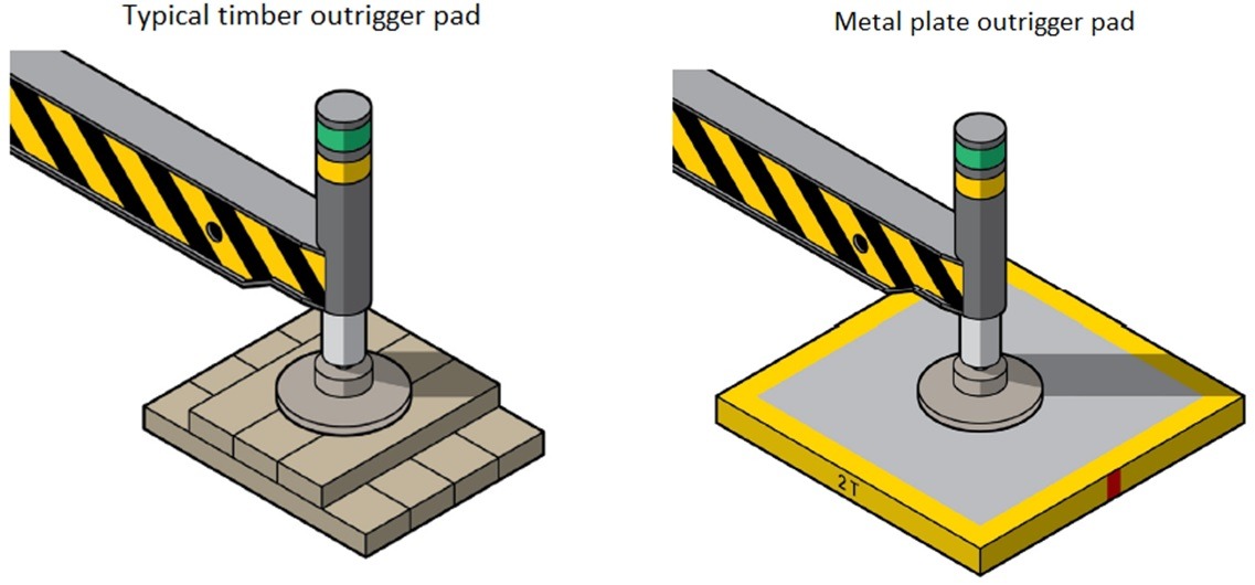
The timbers, pads or bog mats used under the outriggers or stabilisers are appropriate for the type of pump and ground conditions.
Outriggers are extended in accordance with the manufacturer’s load charts.
NOTE: partially extended outriggers may or may not be permitted according to the manufacturer’s load charts. This must be verified on each occasion.
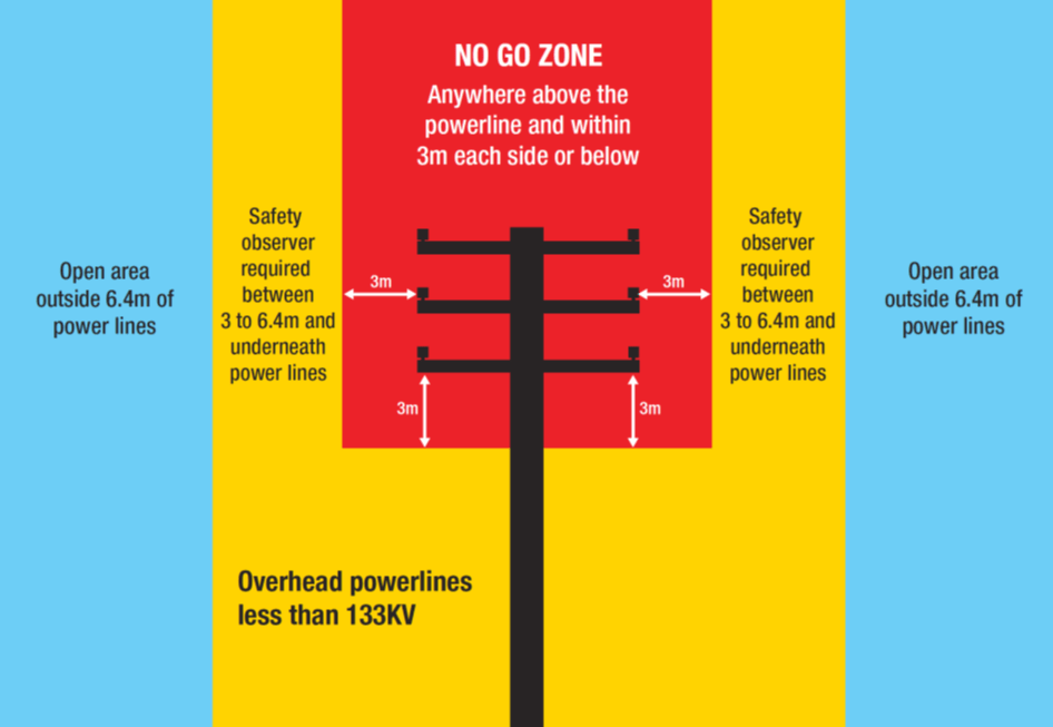
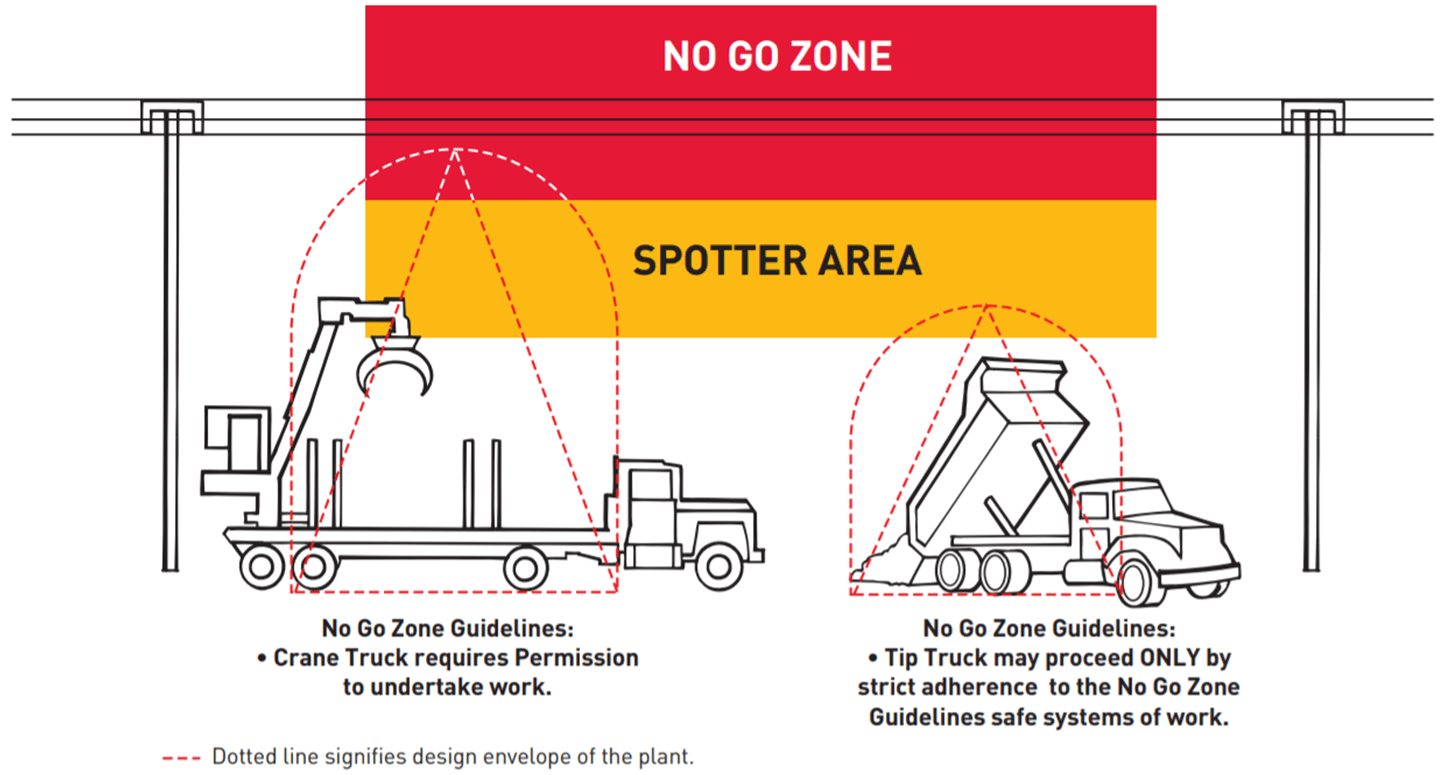
The presence of overhead power lines has been assessed and equipment is positioned outside of the designated no go zone.
Confined Space risk management requirements can vary between jurisdictions and is a specialist area. Refer to SHAPE’s Confined Space Procedure and contact a member of the EHSQ Team if you believe a confined space entry is required as part of your scope of works.
During Pre-Construction, the Confined Space has been identified by the building owner or building management.
The areas identified as confined spaces have been verified by a competent person.
A competent person is someone that holds a certificate/licence or documented evidence of competency.
The project Risk Register and Project Delivery Plan identify the confined space hazard and controls and references the SHAPE Confined Space Work Permit.
Subcontractor SWMS address hazards and controls specific to the location and activity. The SWMS have also been reviewed using the SWMS Review.
The Site Induction identifies confined space locations and site specific requirements.
Subcontractors have been consulted and trained in the SWMS and all documentation required.
All workers have been trained in emergency / rescue procedures and a trial rescue has been enacted and documented using the Record of Toolbox Talk – High Risk Activity Emergency Response. Emergency equipment is in place as per the confined space emergency rescue plan.
All workers hold confined space entry competencies – records have been copied and filed.
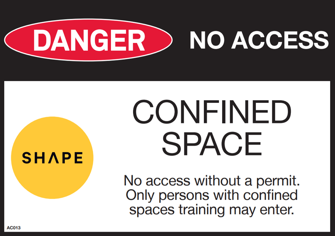
Prior to the commencement of works, confined spaces are clearly signposted with confined space warning signage.
Pre-Start Meetings are held prior to every confined space entry.
The Confined Space Work Permit (including the and confined space entry log) are in place at the point of entry.
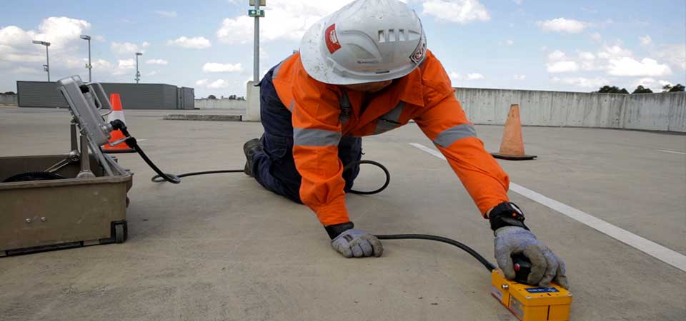
Equipment has been tested for calibration by a competent person prior to use and records are on file.
Air samples have been taken and recorded prior to entry to the confined space.
Air sampling is taken and recorded at regular intervals whilst workers are in the confined space.
Adequate lighting has been installed or provided for the task.
Adequate ventilation is available via natural or mechanical means.
Non-hazardous, non-flammable products are used in place of solvents, adhesives, paint, etc.
OR a risk assessment has been completed when hazardous or flammable products must be used.
Alternative methods of construction have been considered to reduce the need for welding, brazing, painting, cutting, drilling, etc. within the confined space.
If asbestos containing materials have been identified, workers are instructed on asbestos awareness and control measures prior to entry.
Electrical services have been isolated / controlled in the vicinity of the works.
The risk of biological hazards (e.g. mould spores, contaminated water, sewerage) has been considered and managed.
A competent Standby Person is allocated for and identified in the Confined Space Work Permit & SWMS.
Implementation of the work method is reviewed via a Task Inspection during each entry, and controls are amended and communicated as required.
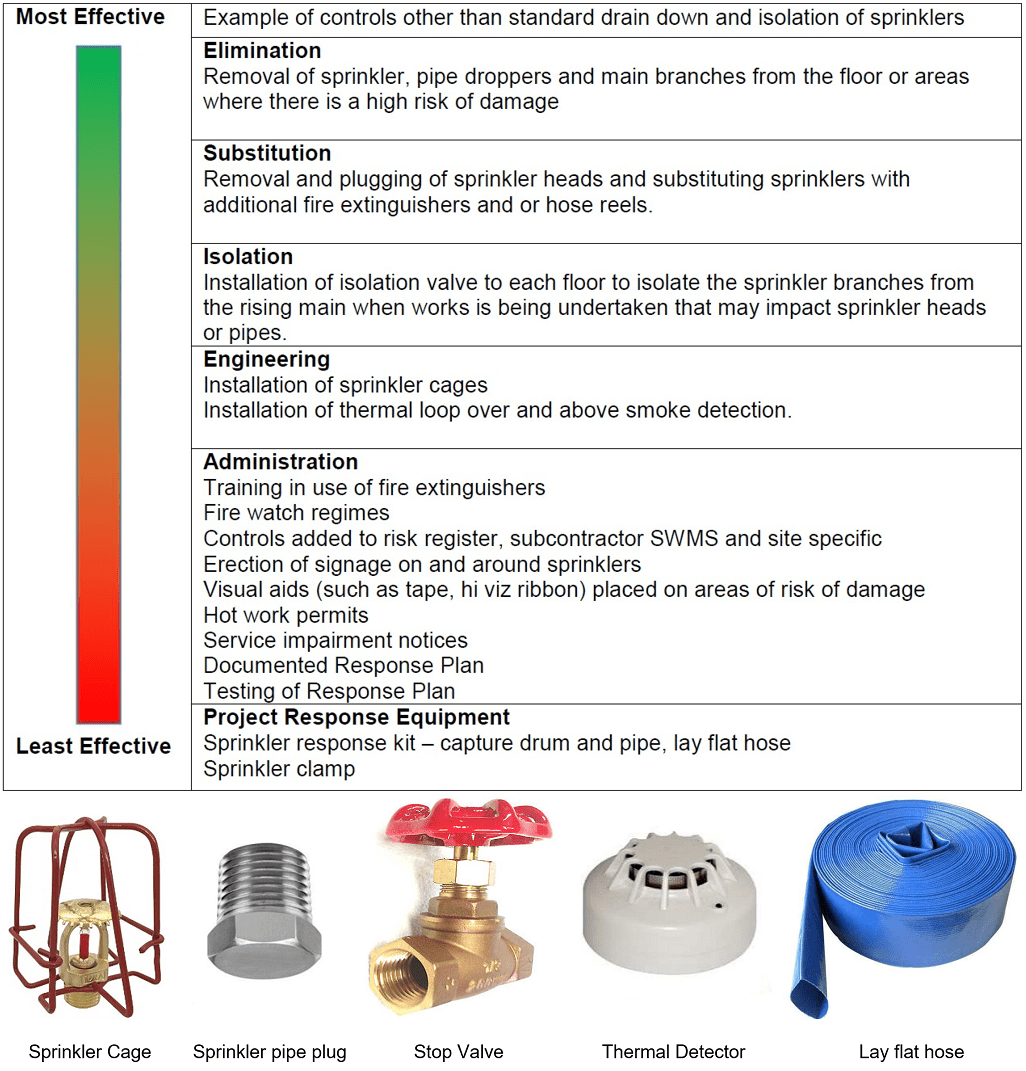
Fire Sprinklers are great for putting out fires and 100% effective at causing thousands of dollars in water damage in a short space of time if activated unintentionally.
During pre-construction, the Project Team has undertaken an inspection of the sprinkler system and other services using the Services Survey to determine and document:
- The location of existing fire sprinkler isolation valve sets
- The method of isolation of the valve sets
- Administration / approval requirements to isolate valve sets
- Emergency contact numbers if emergency isolation of the valve set is required
The information gathered during the Services Survey inspection and the building management tenant/building rules are used to:
- Determine the risk level of damaging sprinklers from works being completed in the area
- Controls to be used to control the risk of damage
- The risk assessment and controls are documented in the Project Risk Register and Project Delivery Plan.
Wherever possible, the risk of property damage through accidental activation / damage to sprinkler heads is to be eliminated.
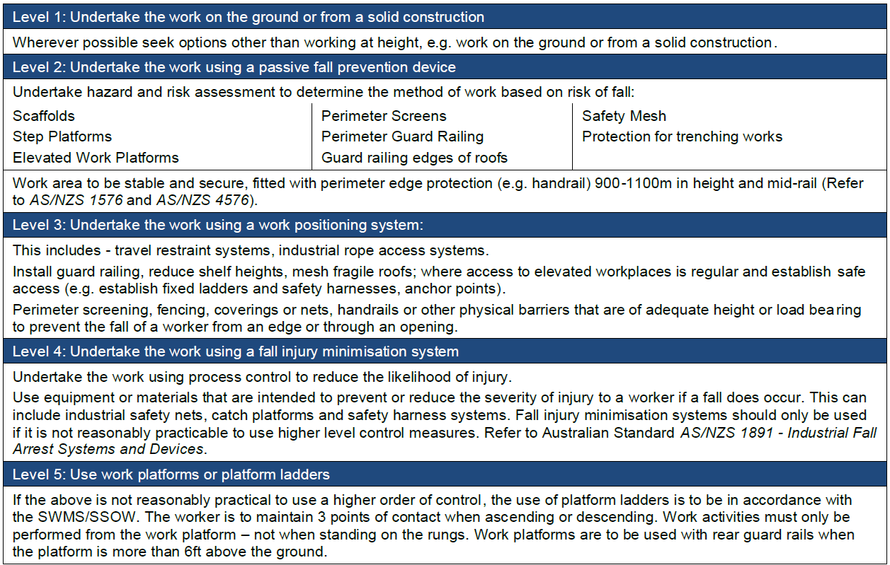
Where Elimination or Substitution cannot be achieved as outlined in this image, SHAPE Minimum Standards require that either an existing fire sprinkler isolation valve set is readily accessible on each floor where work is being performed or a new isolation valve set is installed to provide for immediate isolation in the event of accidental damage.
The installation of a new isolation valve set will require Building Management and Base Building Fire Contractor approval. The project team should endeavour to highlight the benefits of localised isolation valve sets when seeking permission, i.e. localised isolation:
- Avoids the need to complete multiple level fire system drain downs
- Allows fire systems to remain active on all other operational floors
- Provides for a fast response in the event of accidental damage – reducing the risk of impact to building infrastructure and other tenancies
- Reduces the need to access secure areas such as building pump rooms
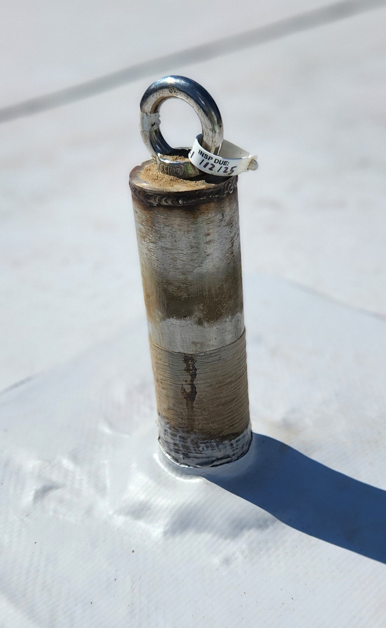
Localised valve sets for the purposes of isolation in the event of accidental damage or for the completion of fire system modifications should be:
- Sign posted and accessible
- Fitted with tamper evident tags or other devices that don’t inhibit emergency use
- Inspected regularly as part of a daily regime to ensure isolation status is known and in accordance with Building Management approvals / permits.
In some cases approval may not be granted (for example due to Building Owner rules, or where the risk of fire outweighs the risk of sprinkler damage), in which case the project team will implement the hierarchy of controls as appropriate and as demonstrated in this image.
Once the controls are determined, the Project Team will then review the controls with the building owner/manager to obtain approval to implement. Should a change be required, the Project Team will assess the changes and determine the best control method and update the project Risk Register.
When controls are agreed to by all parties the Project Risk Register is distributed to all project participants (subcontractors, client, building owner) for their records and action where required such as the creation of Safe Work Method Statements, Risk Assessments or other safe systems of work. Distribution of the documentation will take place through the Procore Submittal process.
Project specific controls to mitigate the risk of damage to sprinkler heads are included in the Site Induction and all workers are inducted into these requirements.
Monitoring and inspection of the controls where sprinkler pipes or heads have been removed will be completed on a daily basis, before and at the end of each shift. These inspections are to be documented in the site diary (notes) or raised as an observation through Procore.
Other controls where the wet fire system is maintained will be completed weekly as a minimum and documented within the Procore Observations tool.
Task Inspections will be undertaken where work is being completed on or around the fire sprinkler system such as:
- Demolition
- Hot works
- Installation of duct or pipe work in ceiling spaces
- Full height or elevated joinery units
- Full height doors and glazing
When works are substantially complete and the risk of damaging the sprinkler system has been reduced, i.e. the installation of ceiling tiles are completed, the use of scaffolds or EWPs have ceased and full height joinery is installed, the controls used to mitigate damage to sprinklers may be removed and standard base building controls may be implemented, i.e. impairment notices and drain downs.
The project team must assess the risk prior to removing the agreed controls and the project Risk Register will be updated. This assessment must include the building owner/manager.
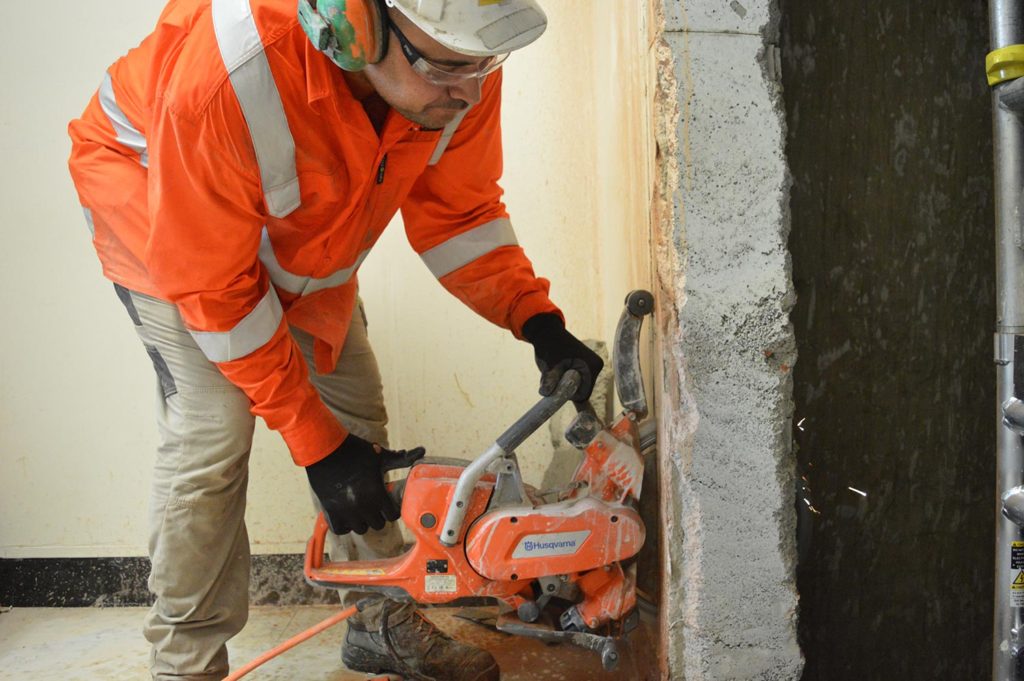
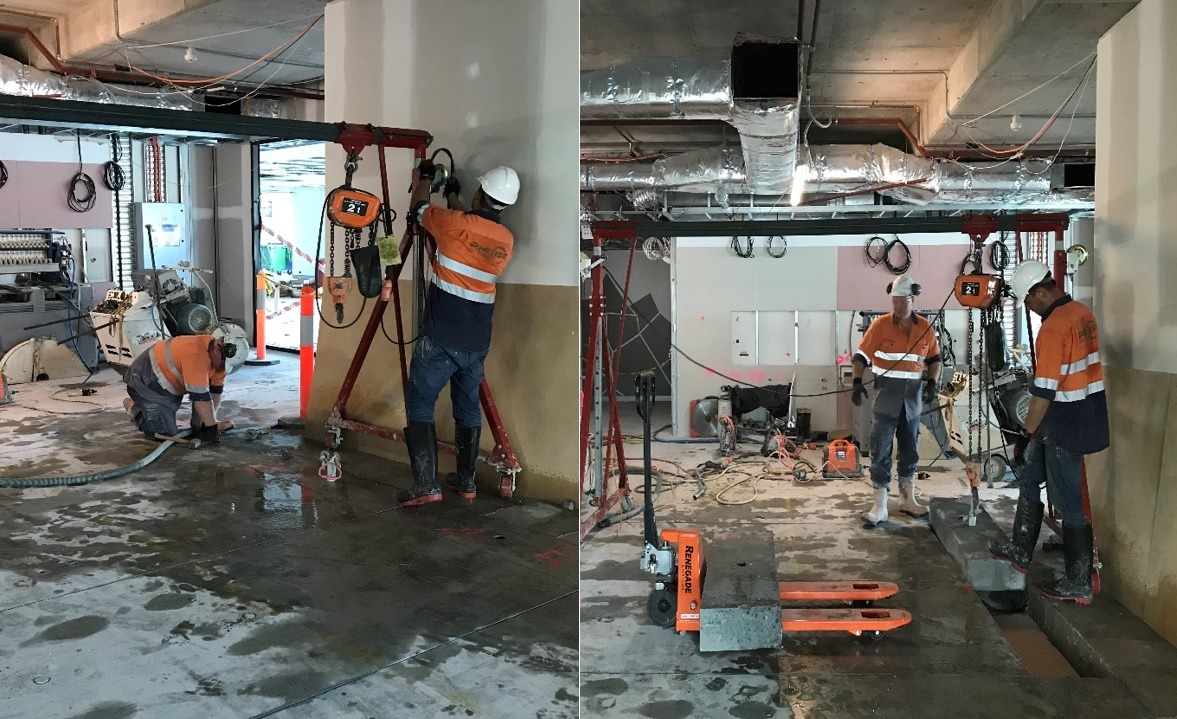
Cutting and Coring activities are all activities that include the use of concrete/masonry cutting saws, core drilling (including hand held and self-propelled or remote controlled equipment), and may also include the use of rotary hammer drills in certain circumstances.
During pre-construction, the project team reviews the scope of works with respect to cutting and coring activities for inclusion into the project Risk Register and Project Delivery Plan. This includes consultation with the building manager regarding building requirements for cutting and coring, as well as the implementation of silica dust controls in accordance with state or territory legislation and the Silica Dust Management SHAPE Minimum Standard.
All relevant information in relation to cutting and coring is detailed within the project Site Induction and communicated to workers through the site induction process.
Subcontractor SWMS are reviewed via the SWMS Review, for inclusion of site specific cutting and coring controls.
Building management are consulted regarding the possibility of in situ services – e.g. power, water, gas, other.
Scanning has been completed and a written report has been provided.
A structural engineer has provided a written approval for the proposed works.
An approved propping design plan has been developed by a qualified structural engineer for all structural cut and core operations.
Structural cut and core operations are defined as:
- Structural demolition, or
- Stair and lift shaft penetrations, or
- Window and door openings through structural and non-structural concrete or masonry, or
- Any penetration or masonry cutting activity that requires temporary or permanent propping to prevent structural failure, damage to a building element or presents a risk to health and safety when not propped.
The propping installation has been inspected and signed off by the designer (structural engineer) prior to cutting or coring activities commencing.
The Site electrician has completed inspections and isolations in accordance with the Permit to Cut or Core, the Cutting and Coring Concrete and Masonry Elements Procedure, and the Electrical Safety Procedure. The site electrician has signed off on the Permit to Cut or Core.
A Plant and Equipment Induction has been completed for all cutting and coring equipment that is self-propelled, powered by a combustible engine or via hydraulic system. All such items have been included in the Plant and Equipment Register.
The Permit to Cut or Core is issued for each cutting and coring activity, and all workers involved have signed onto the permit.
If any changes to the scope of cutting or coring activities are required – the work ceases, the work is reassessed and a new Permit to Cut or Core is issued.
The Permit to Cut or Core is valid for 24 hours only, and the handback section is filled in at the completion of each shift.
RCD protection devices are in place for all power, including 3 Phase power outlets.
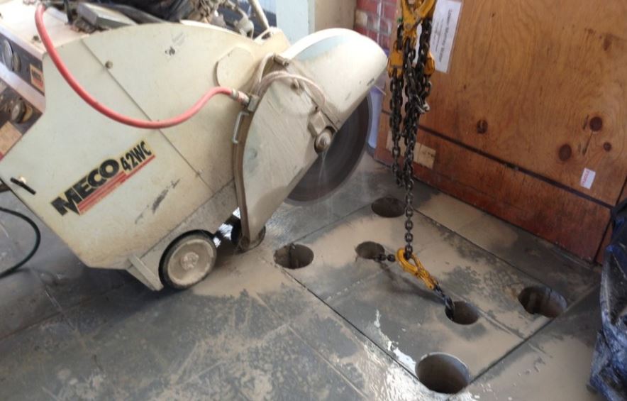
Non-structural core plugs or sectioned building elements are not permitted to free fall, i.e. containment measures are defined in the contractor’s site-specific SWMS
Free fall into catch buckets or trays is not permitted.
Examples of control measures:
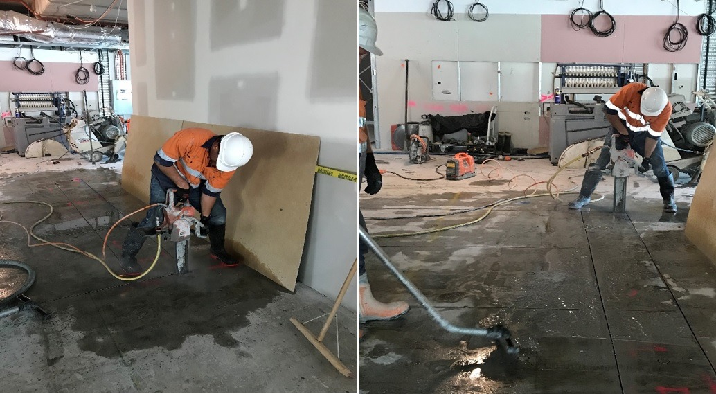
- Structural ply of suitable thickness and dimensions is to be mechanically fixed to the underside of the concrete being cut or cored
- Structural ply of suitable thickness and dimensions is to be back propped using a suitably load rated prop (note: props must be secured / mechanically fixed)
- An approved catch deck has been installed below with sectioned concrete being lifted from above with the use of suitable lifting equipment
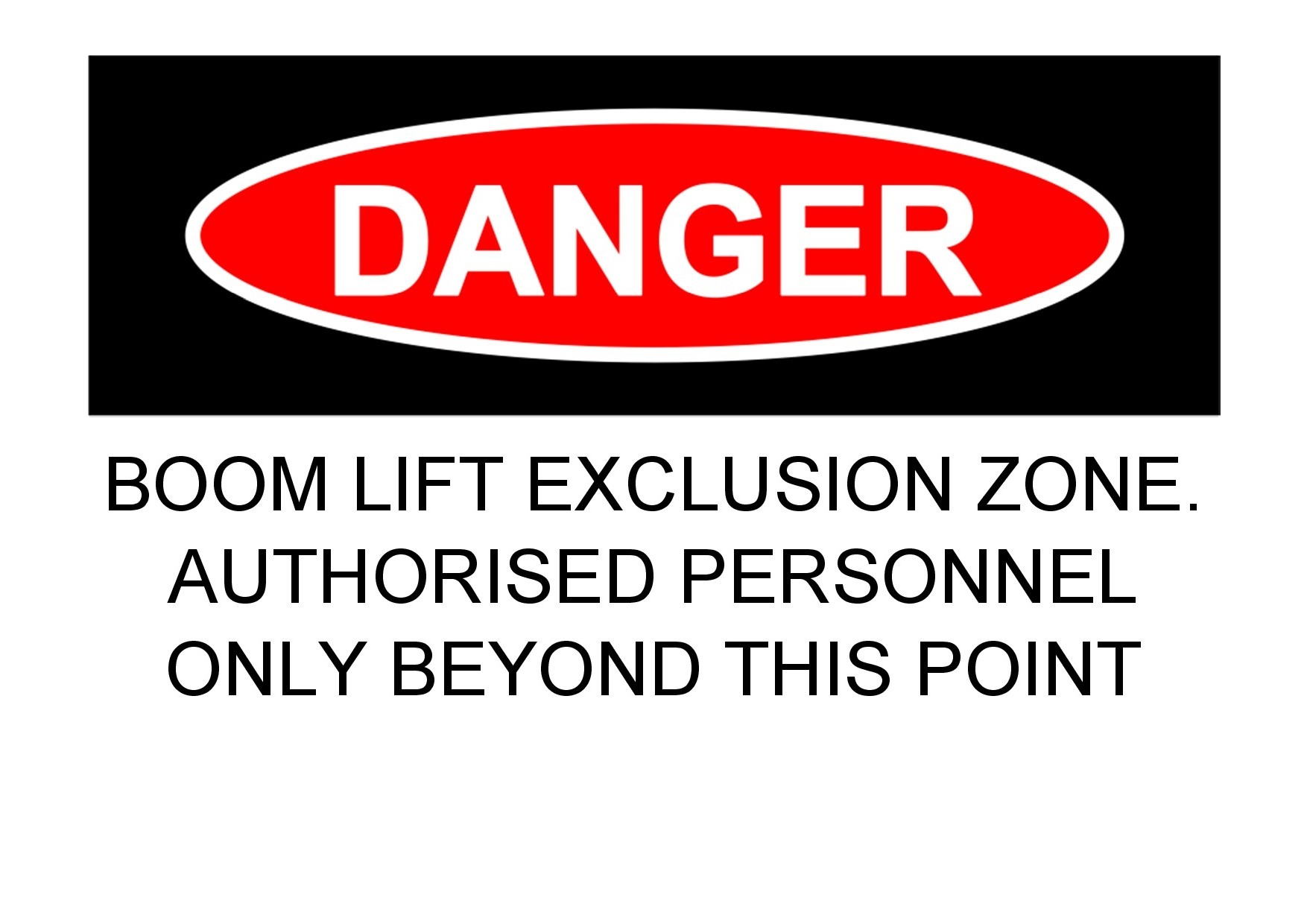
Note: no-one should ever be positioned below the cut or core area – all workers and spotters must be positioned a safe distance outside of the designated exclusion zone.
A works methodology is submitted with all cutting and coring involving the sectioning and removal of concrete and masonry elements (e.g. stair penetrations, demolition of precast concrete walls).
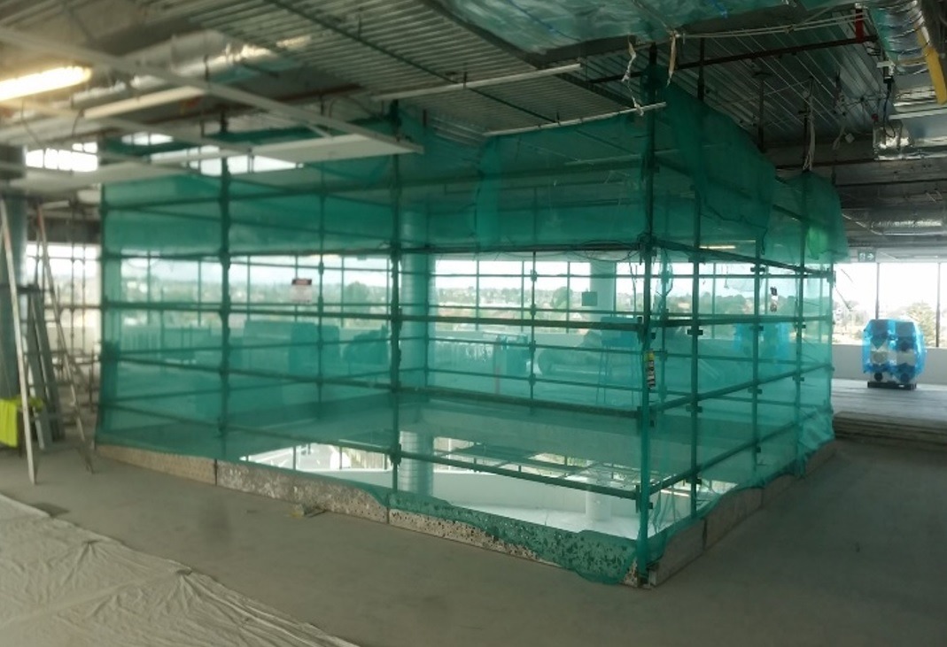
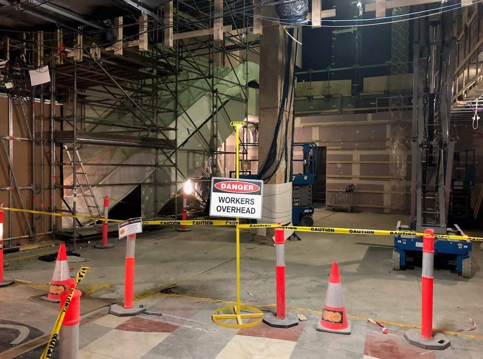
Exclusion zones / barriers are established below all cut and core locations.
Warning signage is posted around exclusion zones prior to the commencement of works.
Waste water from the cutting process is captured and disposed of properly, i.e. not in toilet pans, urinals, bathroom sinks, storm water drains, etc.
A trained and competent spotter is positioned below the cut and core locations, outside of the exclusion zone.
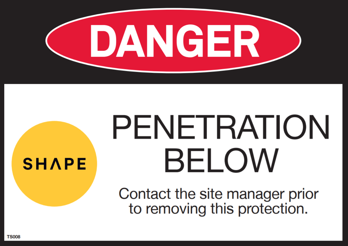
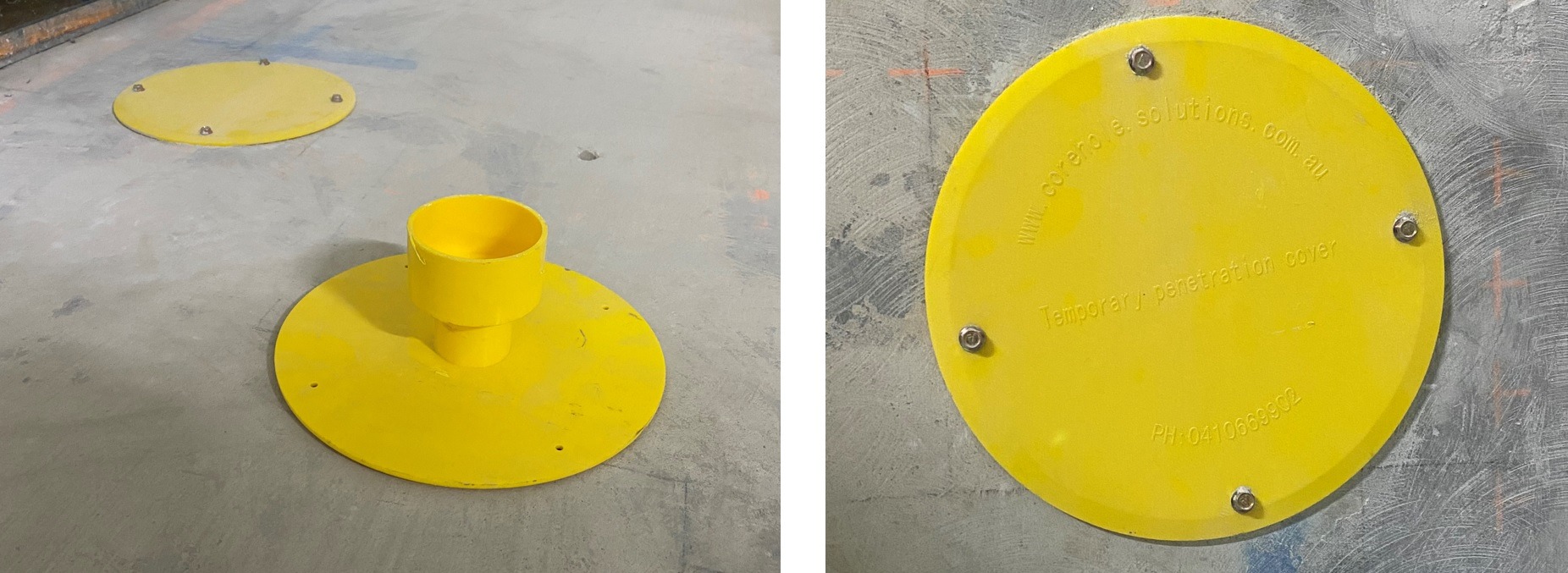
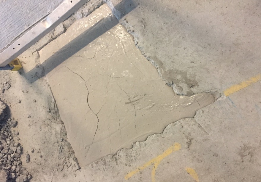
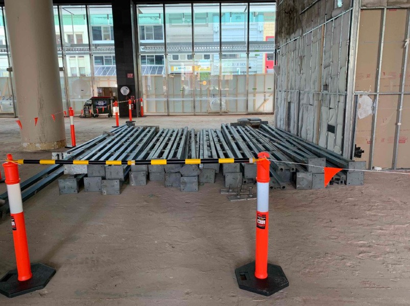
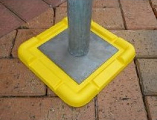
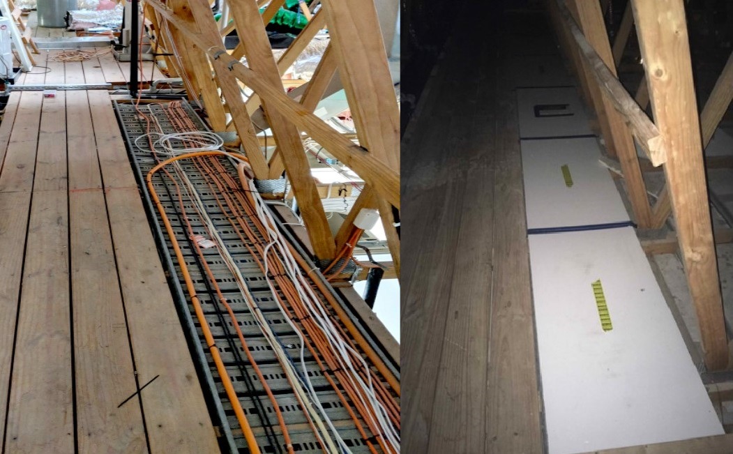
Fixed covers or certified barriers are in place around all penetrations and openings. For core holes, proprietary temporary core hole covers are preferred, such as those shown in this image.
Note: always assess penetration covers for load rating / trafficability requirements in consideration of people, plant and equipment use.
A Task Inspection is completed for high risk cutting and coring activities, to monitor compliance with the SWMS and work methodology.
Working near live electrical services is one of the key hazards on commercial fitout and refurbishment projects, and requires detailed planning and risk assessment prior to the commencement of work.
During pre-construction, the project team reviews the scope of works with respect to electrical hazards and controls, for inclusion to the Project Risk Register and Project Delivery Plan.
Only licensed electricians are permitted to install, modify, test or certify electrical installations. Electricians must be trained in accordance with the both the type of work being undertaken and the jurisdictional requirements.
The licensed electrical contractor undertaking the Electrical Survey has provided a task-specific SWMS prior to undertaking the survey. The SWMS are reviewed and approved using the SWMS Review.
Prior to conducting the Electrical Survey, electrical workers receive the Site Induction and the Record of Toolbox Talk – Electrical Contractors. These requirements apply to all cabling contractors, i.e. fire services, security, mechanical controls, BMS, etc. as the project progresses. A copy of the Electrical Safety Procedure is appended to the Record of Toolbox Talk – Electrical Contractors.
A separate Electrical Survey is completed for each project stage, level and work area.
Electrical Survey(s) are reviewed, make safe actions are verified as being completed and signed off by all parties prior to proceeding with other trade activities.
Mechanical electrical services are surveyed and controlled for each project stage, level and work area within the Electrical Survey.
After the initial Electrical Survey has been completed, where there has been increased or new electrical risks identified the Project Risk Register and Site Induction are updated.
Prior to proceeding with electrical strip out or demolition activities, the electrical contractor has provided task-specific electrical SWMS based on the scope of works identified in the Electrical Survey.
Switchboard work is performed with full isolation of power from the downstream supply source.
An Electrical Deviation Risk Assessment is completed and approved by the SHAPE General Manager or delegate, in the unlikely event that work needs to be performed on a partially live switchboard (i.e. where a live feed to the switchboard is present).
If an Electrical Deviation Risk Assessment is to ever be approved, a detailed SWMS and Emergency Response Plan (which includes provisions for a trained LV rescue person with an LV rescue kit to monitor the activity) must also be endorsed by the relevant SHAPE General Manager or delegate prior to works commencing.
Where fuses are to be removed from T-OFF boxes as a method of isolation, the SWMS details specific hazards and controls to be implemented – i.e. use of insulated tools and equipment, trained electrical rescue personnel, electrical rescue kit, etc.
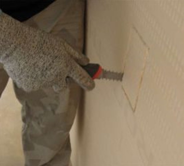
Existing cabling is removed from all partitions, ceilings, bulkheads and voids prior to other trades accessing these areas. This may require the electrician to break open these restricted spaces for a visual inspection and to remove and strip cables.
Temporary Switchboards – refer to the Temporary Switchboards SHAPE Minimum Standard.
Construction Lighting – refer to the Construction Lighting SHAPE Minimum Standard.
Construction Wiring and Extension Cord Sets – refer to the Construction Wiring and Cord Extension Sets SHAPE Minimum Standard.
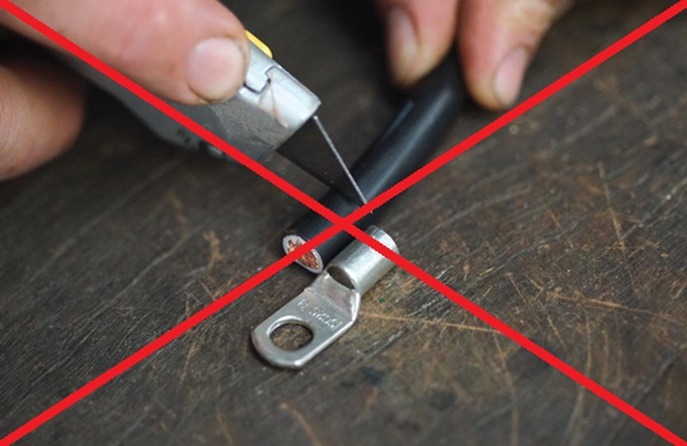
Extra Low Voltage (< 50V AC or < 100V DC) cable ends are terminated by use of terminal connectors – this includes fire, security, mechanical controls, nurse call systems and similar.
All existing Low Voltage (50 to 1000V AC, or 100 to 1500V DC) cable ends that are not being removed or stripped out are junction boxed.
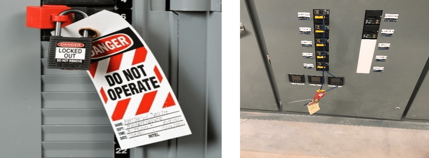
Circuit breaker isolations are locked with a propriety locking device including a padlock or cable lock and electrical tag.
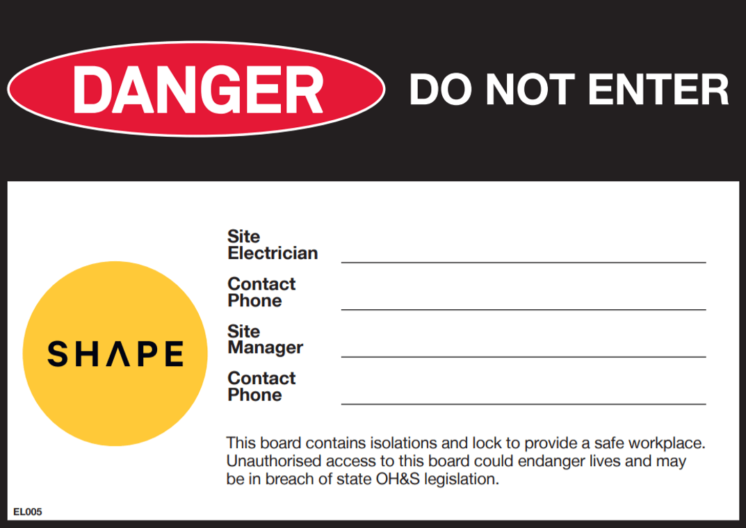
SHAPE switchboard signage is posted on the switchboard door or escutcheon panel when isolations or other work activities are taking place on the switchboard.
When circuit “tails” are removed from the switchboard, an electrical tag or label is assigned to each breaker identifying that tails have been removed. This may also be achieved where the majority of tails are removed via an updated circuit legend or other method of labelling.
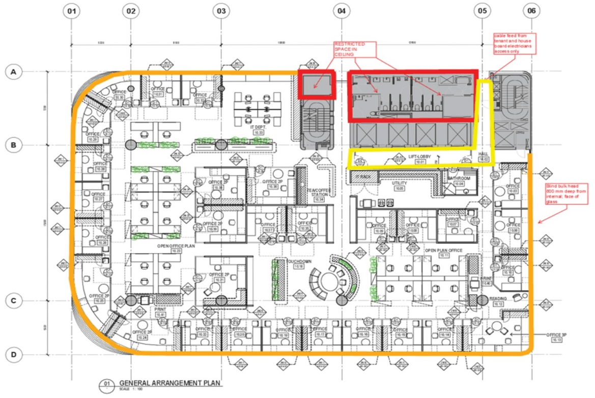
Where live cables or other electrical hazards are present, Restricted Space signage is posted at regular intervals at the location of the hazard to ensure high visibility. These locations are marked up on a drawing and form part of the Electrical Survey and the Site Induction.
NB Restricted Access signage placed on a partition wall to reflect a ceiling hazard is not appropriate.

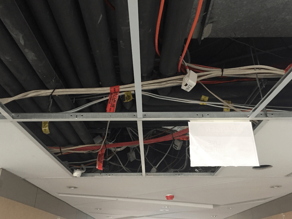
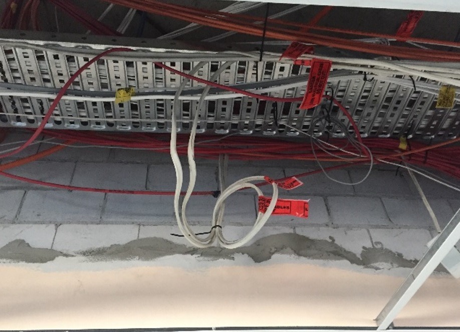
SHAPE Red warning tape – “DANGER – Live Electrical Cables – Do Not Cut” is placed at 2m intervals to all existing cables that are remaining LIVE.
Always consider locations outside of the site envelope such as building core areas, lobbies, toilet facilities, that may need to be accessed for service runs to risers and plant rooms, etc.

If work must be performed within 1 metre of LIVE Low Voltage (LV) cables (≥50 V AC to 1000 V AC, or 120 V DC to 1500V DC), and these LV cables cannot be isolated, relocated or RCD protected, then the cables must be managed as follows:
- Physical protection suitable for the type of damage that may occur must be installed around the cable in the vicinity of the risk (i.e. the immediate area where the work is being carried out and extending to at least one meter outside the work zone);
- The cable and conduit must be labelled with Red “Live Electrical Cable – Do Not Cut” tape at a maximum spacing of 2.0m;
- Ceiling signage must be installed to alert workers of the potential risk in the work area.
External work areas are assessed for overhead and underground services hazards. Hazards and controls are detailed within the Electrical Survey and associated contractor SWMS.
Use of Plant and Equipment in proximity of overhead or underground power has been risk assessed and controls implemented (e.g. exclusion zones, spotters, supply authority permits).
When work is to be performed in proximity of live electrical apparatus (at a defined safe approach distance and in accordance with the supply authority permits), a risk assessment will be undertaken and safe systems of work developed (including emergency response procedures) in consultation with the workers involved, the site electrician and when required the energy authority or provider.
Workers involved with work in proximity of live electrical apparatus will need to provide evidence of competency in UETDREL006 – Work safely in the vicinity of live electrical apparatus as a non-electrical worker, or an equivalent / superseded competency unit such as UETTDREL14, UETTDREL14A, UETTDREL04B, UETTDREL04A.
Note: Work in proximity of live electrical services may include activities such as telecommunications, vegetation control, scaffolding, rigging, lifting operations, painting or any other activity that requires working safely and complying with requirements, established procedures or safe systems of work near live electrical apparatus by a non-electrical worker.
Ongoing review of electrical hazards and controls takes place via site walks, Procore Hazard Observations, Procore Site Inspections and Task Inspections.
New or increased electrical hazards are risk assessed and any changed conditions communicated via Toolbox Talk. Changes to electrical safety controls are reflected in an updated Site Induction.
Prior to energising new circuits the licensed electrician performs testing in accordance with the Testing, Energising and Commissioning Plan. Test results are provided by the licensed electrician prior to and after energising. Each electrical services trade completes a separate Testing, Energising and Commissioning Plan prior to energising their installation, e.g. fire services, mechanical, security electricians, etc.
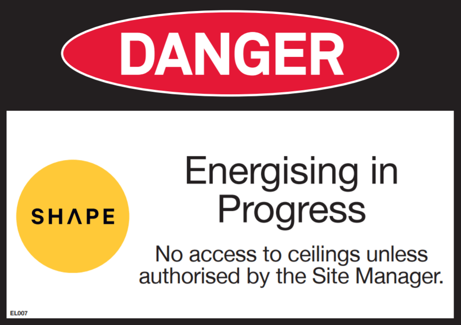
Prior to energising, Energising in Progress warning signage is installed at regular intervals throughout the site and at the site entry point.
Prior to energising, all workers have participated in the Record of Toolbox Talk – Electrical Energising to communicate electrical hazards and changed site conditions in relation to energising activities. This may include changes to temporary power and lighting.
Once energising has commenced, no trades other than electricians are allowed in the energised ceiling space without a documented risk assessment completed for the area that needs to be accessed, and the controls identified in the risk assessment have been put in place.
Construction lighting supplied via temporary construction switchboards is the preferred method of site lighting for SHAPE projects – refer to the SHAPE Electrical Safety Procedure. This SMS is to be reviewed in conjunction with the Temporary Switchboards SMS and Construction Wiring and Cord Extension Sets SMS.
Prior to commencing the installation of construction lighting, the project team reviews the project documentation and plans for the location of construction light fittings to ensure adequate lighting levels will be maintained as the project progresses.
NB – the reliance on task lighting for later stages of the project as partitions close up is not preferred.
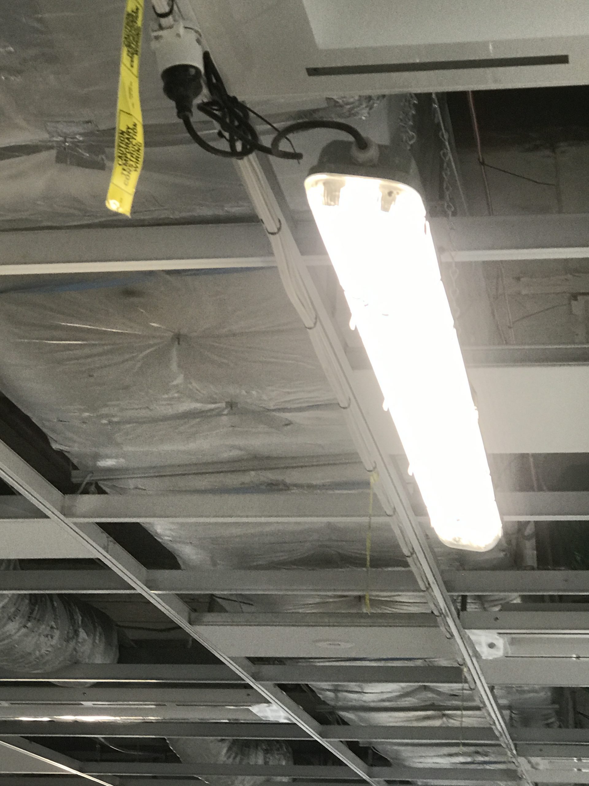
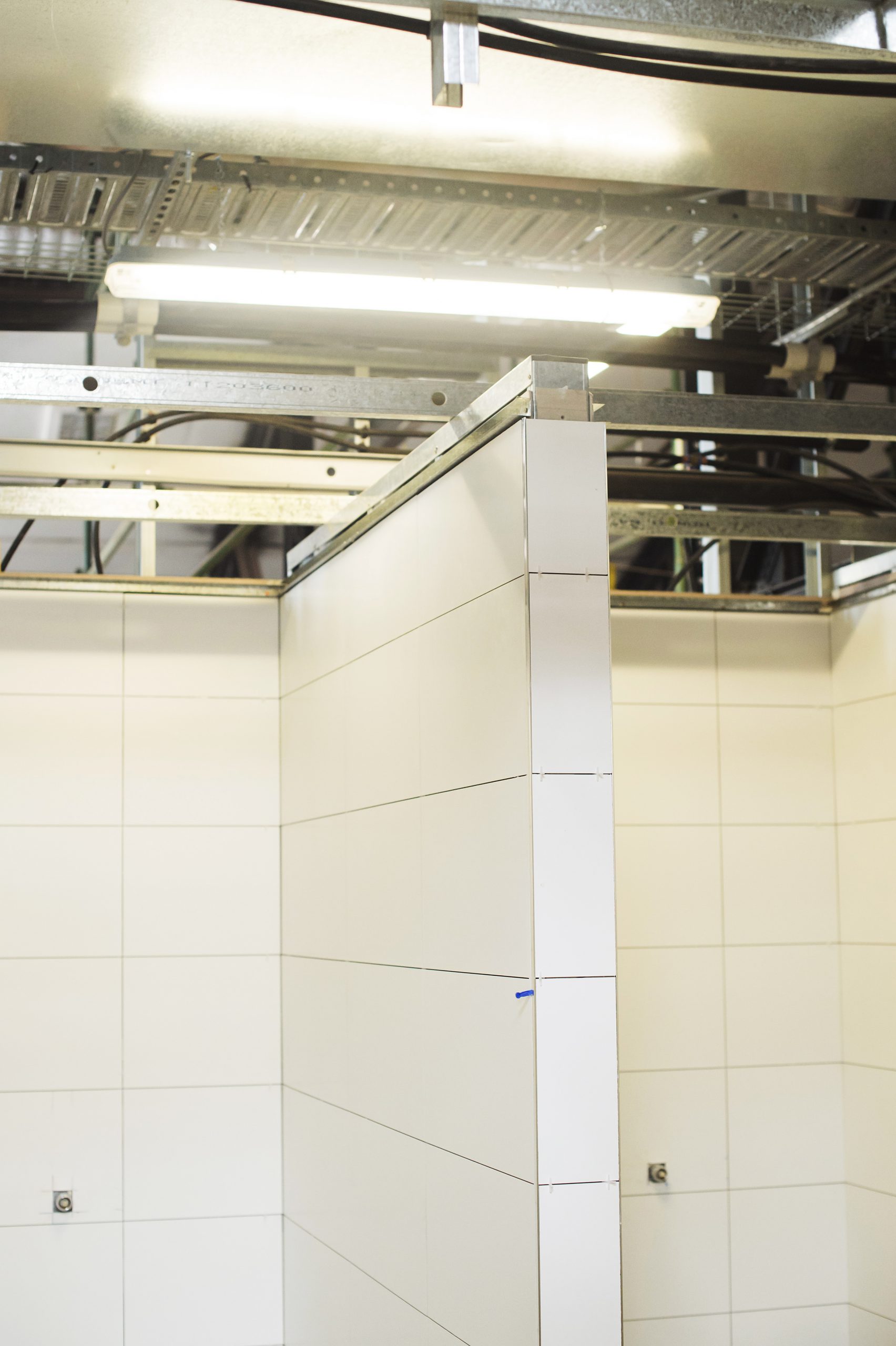
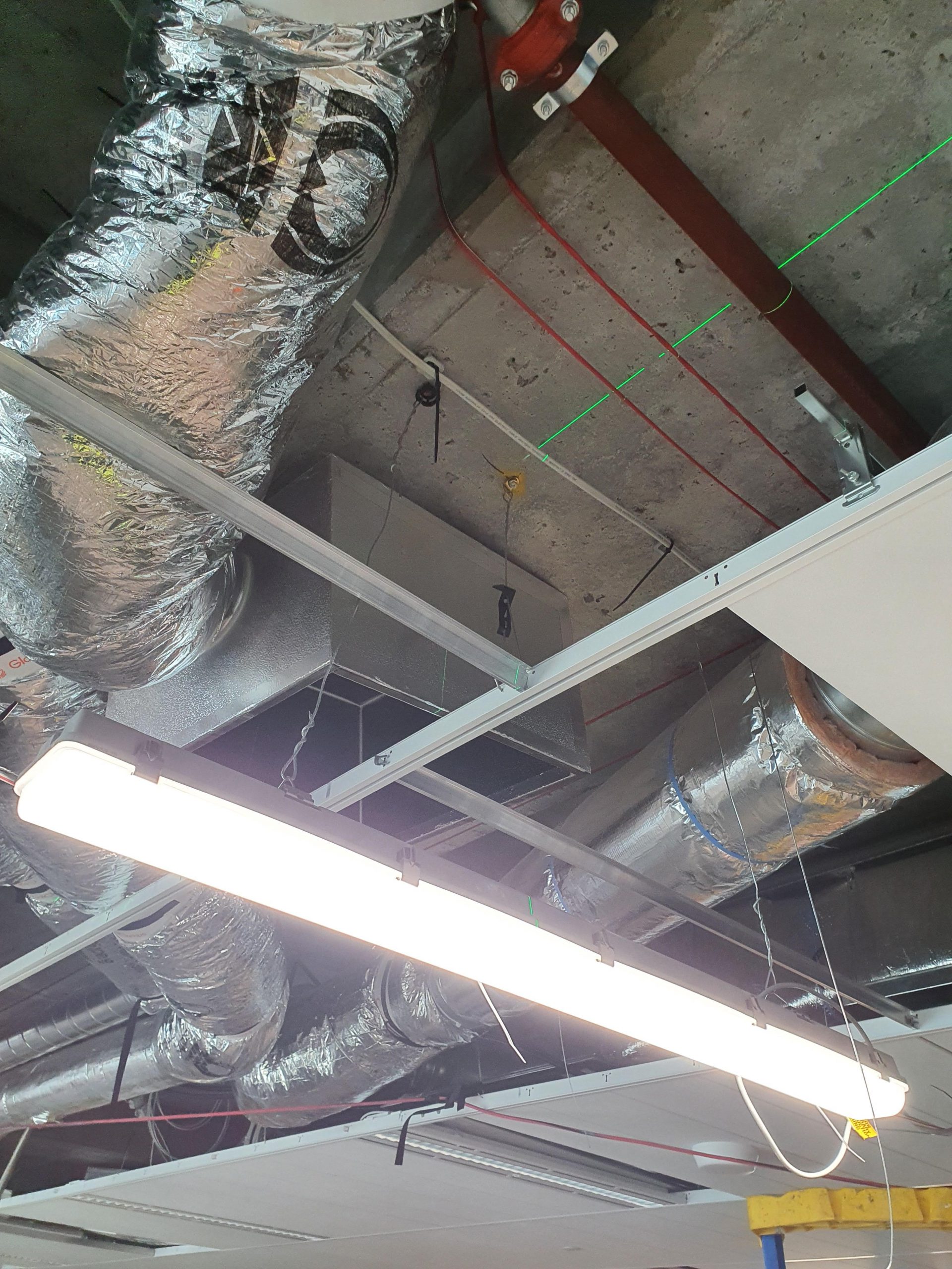
Construction lighting is fitted below ceiling levels, allowing lighting to be maintained throughout the life of the project without impacting lighting levels when the ceiling is closed.
Construction lighting to areas with finishes such as wall and floor tiles is extremely important to ensure a high quality finish and will usually require a lux level that replicates the final lighting levels.
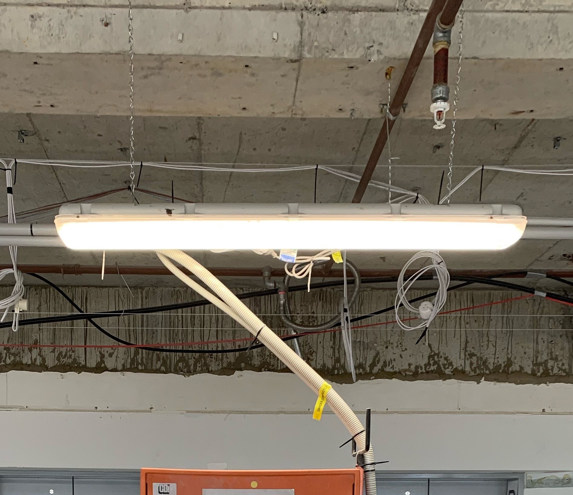
Lamps / globes in light fittings are protected against mechanical damage, i.e. wire cages or anti vandal style diffusers.
All light fittings are suspended from jack chains or fixed to stable building elements.
Office light fittings are not used as temporary construction lighting as they do not comply with the Australian Standard for construction lighting.
Where more than one lighting circuit is installed, the lighting circuits are distributed between RCDs.
Adequate lighting is provided to all work areas and other locations including stairways, fire exits, passageways and adjacent to switchboards to allow safe access and egress.
Exit lighting with battery back-up (or self-illuminating exit signage) is posted so that it is visible from all locations on site.
NB the project floor plan / partition layout must be considered when planning the position of emergency exit lighting and signage to ensure adequate lighting is available as the project progresses.
Emergency lighting with battery back-up is installed at least every fourth light, above temporary switchboards and within 2 metres of exit signs.
Other types of lighting:
Portable luminaries / task lights (e.g. flood light tripods) have protection / mechanical guard to the lamp and adequate stability, or are secured to a suitable structural element.
Task lighting is the least preferred option for site lighting.
Existing light fittings may be used for lighting in certain circumstances such as minor works activities if supplied via an RCD protected circuit. Refer to the Electrical Safety Procedure for the definition of minor works where this may be permitted.
Existing light fittings may not be used if they have been removed from the ceiling grid.
This SMS is to be reviewed in conjunction with the Temporary Switchboards SHAPE Minimum Standard, Construction Lighting SHAPE Minimum Standard and Electrical Safety Procedure.
Construction wiring is segregated from permanent / existing wiring.
Construction wiring is not fixed to free standing fences that have no fixed posts (or equivalent means of support).
NB this may include certain types of hoarding and other temporary structures.
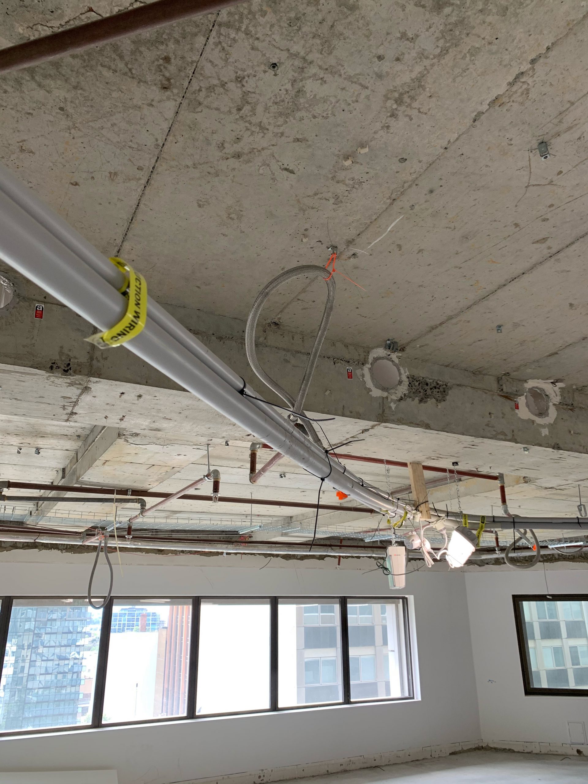
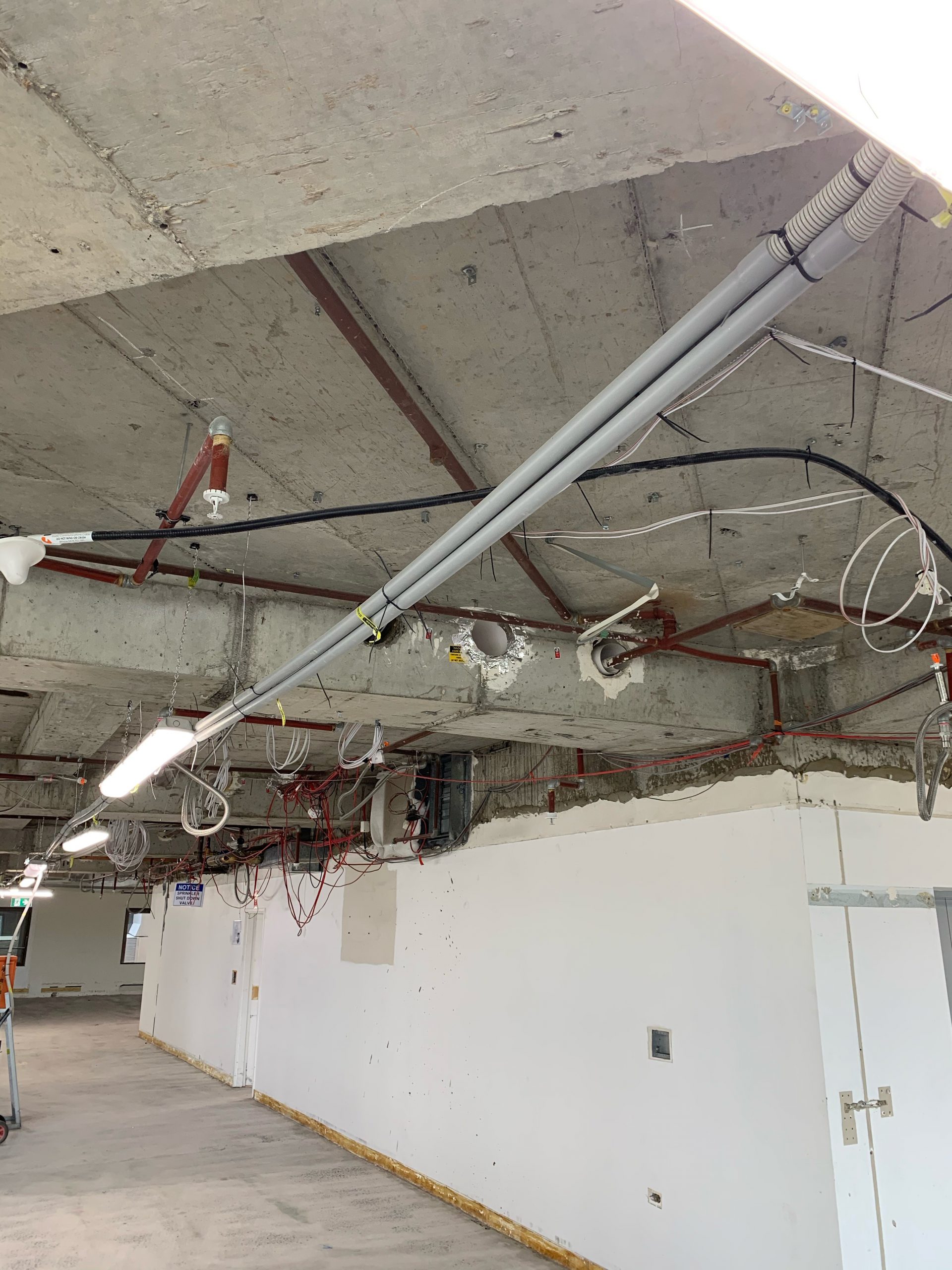
Construction wiring is supported by dedicated catenary wires, cable clips or cable tray – the use of existing metal services, hangers, ceiling framing, etc. is not permitted.
Construction wiring is physically protected where there is a risk of mechanical damage – using medium duty, heavy duty or corrugated conduit, armoured cable, or flexible electrical hose – unless the risk assessment shows such protection is not necessary to maintain electrical safety.

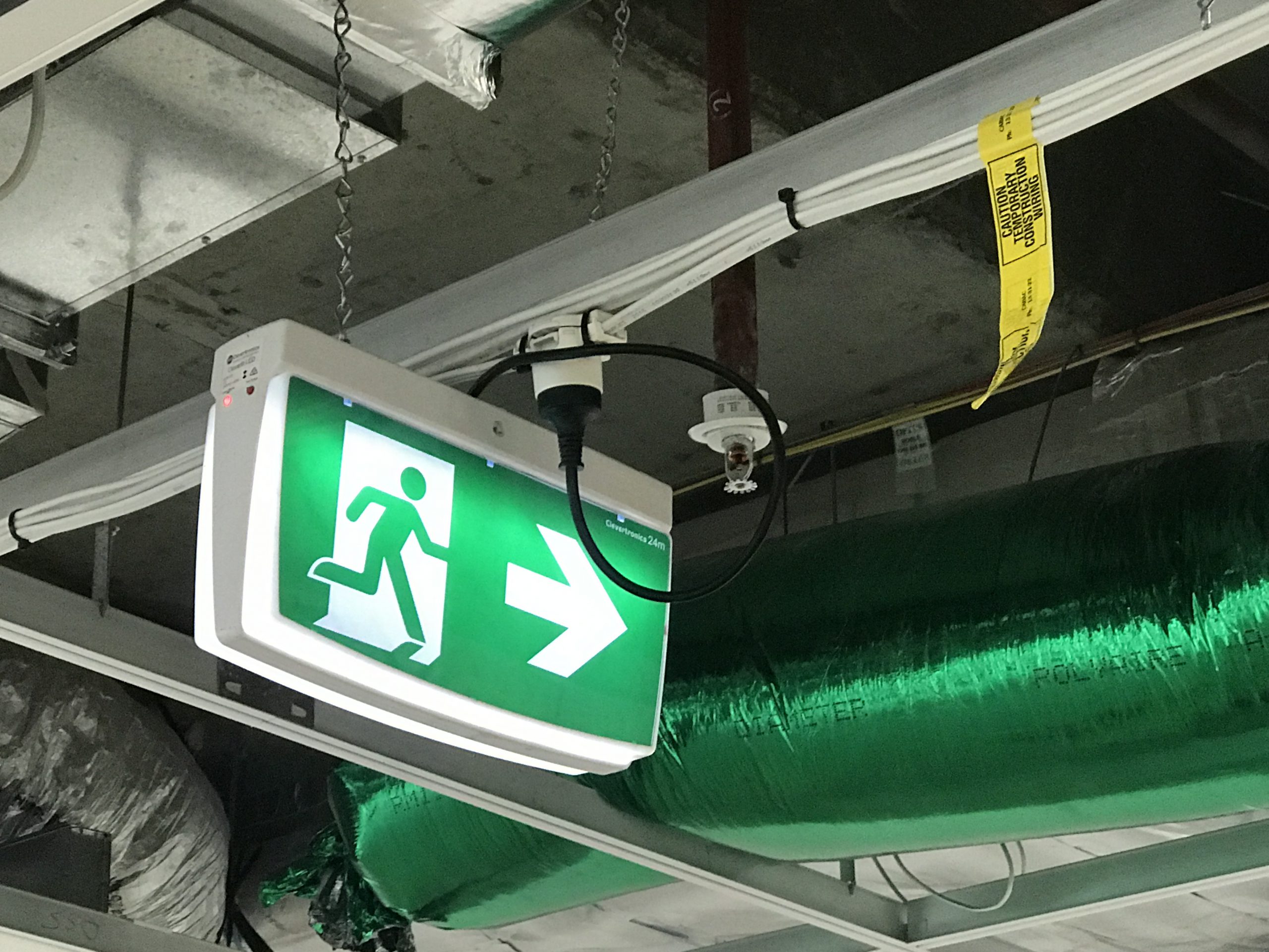
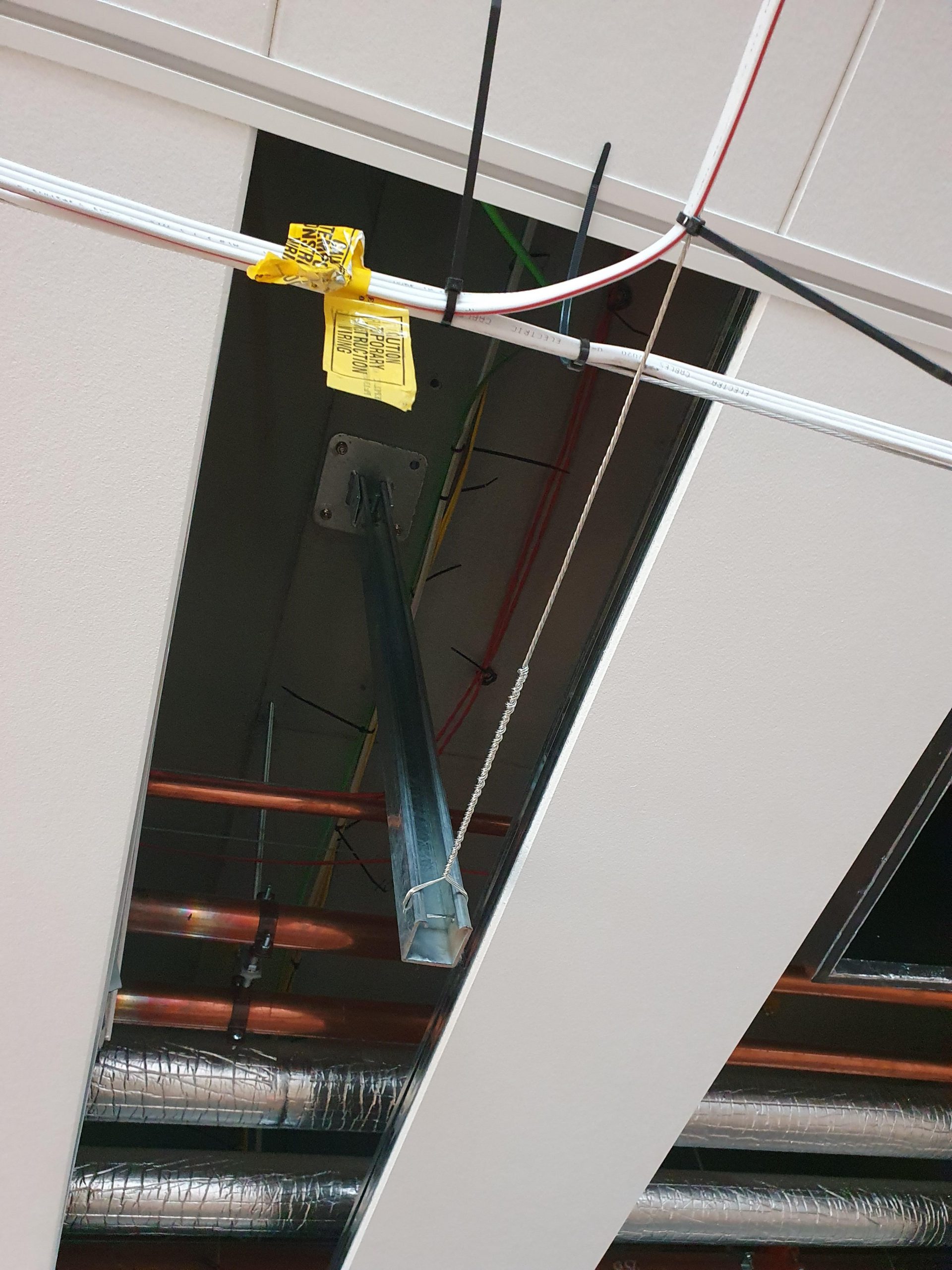
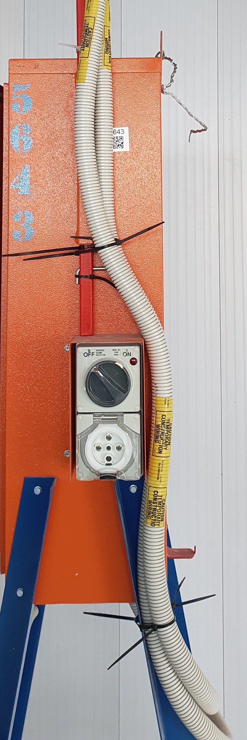
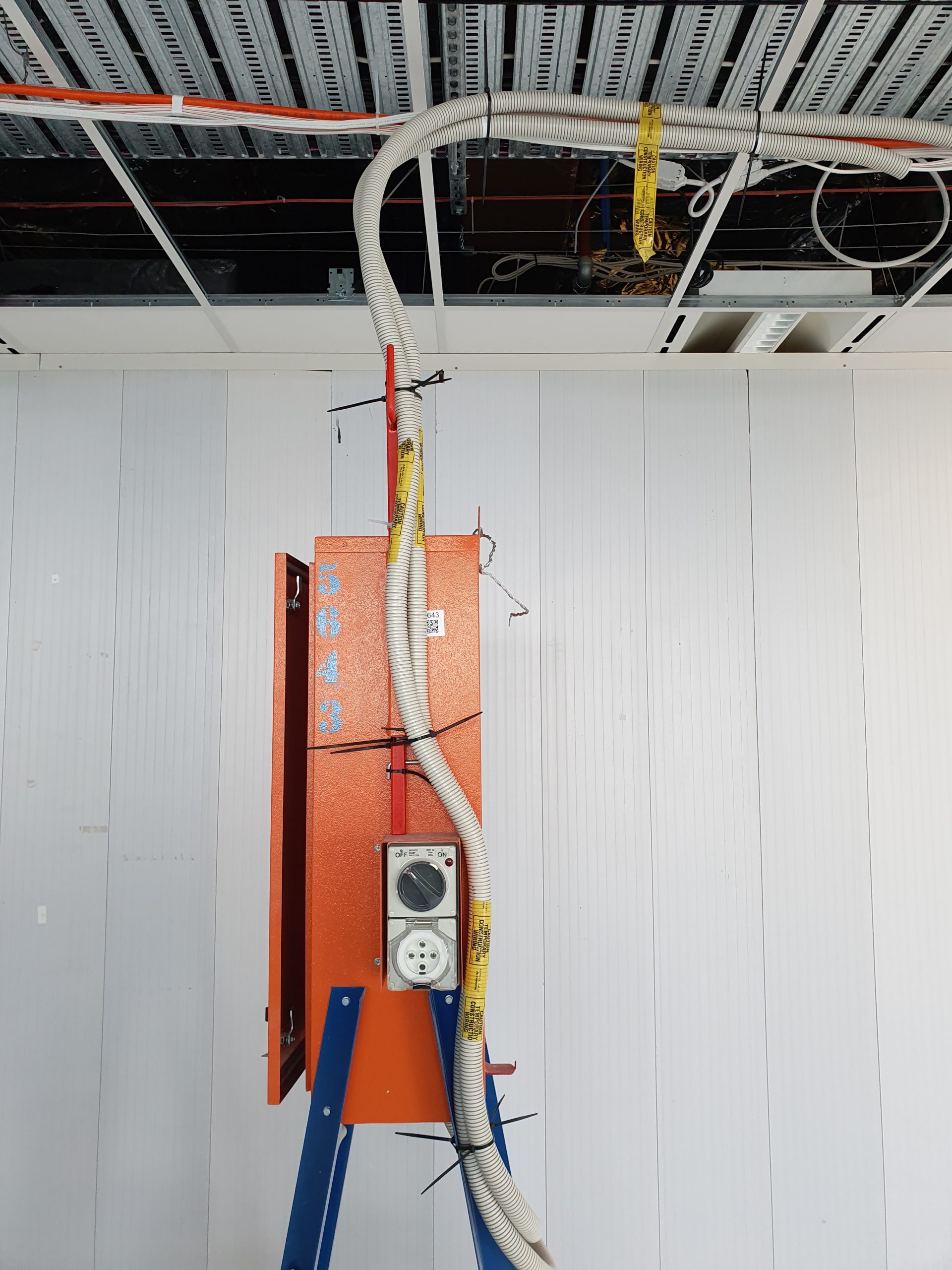
Construction wiring is marked with iridescent yellow tape with the words ‘construction wiring’ spaced at intervals not exceeding 4 metres.
NB – the use of SHAPE Red warning tape is not permitted on construction wiring.
Construction wiring is positioned to avoid crossing roadways or access ways where cranes, high loads or heavy machinery may travel. If this is not possible, an effective means to minimise the risk of vehicular contact with the overhead wiring system is provided and detailed within the Electrical Survey.
Leads are only used when supplied by a temporary construction switchboard on the same level. If this is not achievable, a documented risk assessment must be undertaken.
Switchboards are supplied by a new run of cable which has a minimum cross sectional area of 4mm2.
Flexible cords, cord extension sets, flexible cables and accessories:
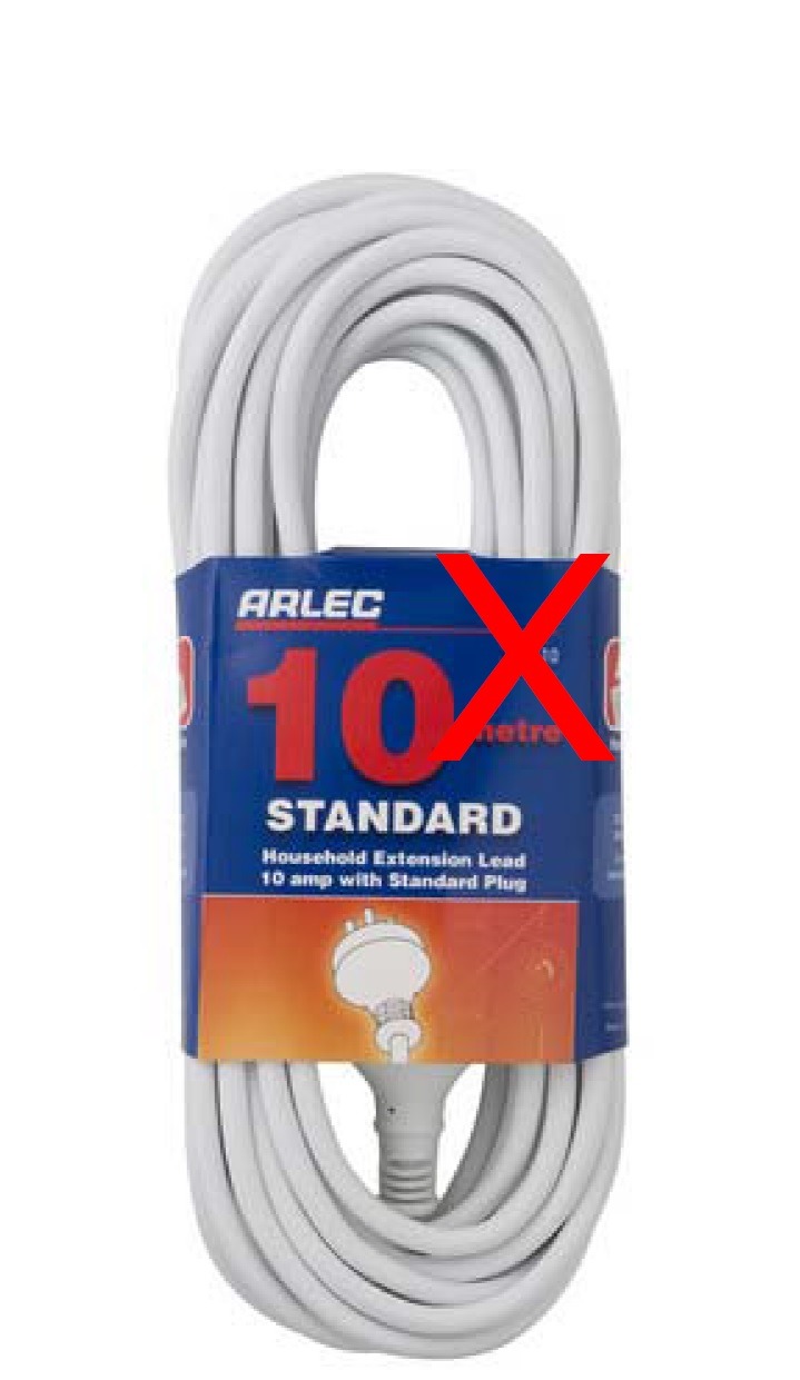
Flexible extension cords have heavy duty sheathing.
Domestic type flexible cord extensions are not used.
As a general rule, 10A cord extension sets with a cross-sectional area of 1.5mm2 should not be longer than 20m. If the supply cord of the tool is greater than 2m, then this must be included when calculating the maximum length of 20m.
Extension leads are supported on insulated hooks or lead stands.
Cord extension sets emanating from the temporary construction switchboard are wrapped around the insulated tie bar, and then supported on an insulated support directly above the switchboard at a minimum of 2.2m above the floor level.
Cord extension sets are not in contact with any conductive building materials or heat generating equipment (e.g. ceiling grid, temporary construction lighting, scaffolding, sprinklers, etc).
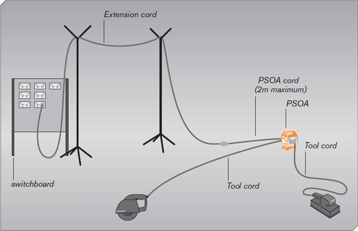
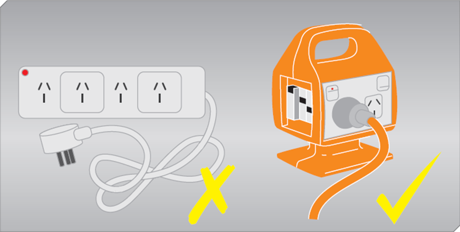
Portable RCD boxes (Portable Socket Outlet Assemblies or PSOAs) are RCD protected and meet the requirements of AS 3012.
Portable Socket Outlet Assemblies (PSOAs) and cord extension sets display a current test tag. New in-service tools and equipment are also tagged.
Existing power supplies should only be used for minor or short duration works (e.g. 2-3 days and do not have any demolition or building works).
This can be achieved via:
- RCD located at the existing switchboard supplying the final subcircuit, OR
- A Portable Socket Outlet Assembly (PSOA) plugged directly into the socket outlet.
The use of Temporary Switchboards is the preferred method of power supply for SHAPE projects – refer to the SHAPE Electrical Safety Procedure. This SMS is to be reviewed in conjunction with the Construction Lighting SMS, and the Construction Wiring and Cord Extension Sets SMS.
During pre-construction, the project team reviews the scope of works with respect to power and lighting supply requirements, for inclusion into the Project Risk Register and Project Delivery Plan.
As part of the site-specific Electrical Survey the required number and locations of temporary switchboards for the project is determined.
Switchboards are located / positioned to suit the maximum flexible cord lengths – generally no more than 20 metres.
Power supply for trade requirements has been considered including mixing areas, battery stations and 3 phase power for equipment such as floor grinders.

Domestic switchboards are not used. All switchboards fully comply with AS/NZ 3012 Electrical installations – Construction and demolition sites, and are installed in accordance with AS/NZS 3000 Wiring Rules.
After their initial installation, all switchboards are verified (inspected and tested) in accordance with AS/NZS 3000 and AS/NZS 3017. The testing equipment used, serial number and calibration date/certificate are documented with the test records, which have been provided to SHAPE prior to use. Re-testing is completed every three months.
The SHAPE Site Manager uses the Electrical Survey or this Temporary Switchboards SHAPE Minimum Standard to check all switchboards prior to their use on site, and regularly thereafter.
Final sub-circuits are protected against overload and short circuit by a circuit breaker RCD protection with a maximum rated residual current of 30 mA, which operates in both the active and neutral conductors. Lighting circuits are distributed between RCDs to minimise the impact of the operation of a single RCD.
Switchboard RCDs undergo calibration testing every 3 months (every 1 month in Victoria). Test results are provided to the SHAPE Site Manager.
Push-button RCD tests (by users) are performed at least once per day prior the use of portable RCD equipment.
Switchboards are readily accessible and clear from obstructions. A minimum clearance of 600mm is maintained to allow unimpeded opening of the switchboard door.
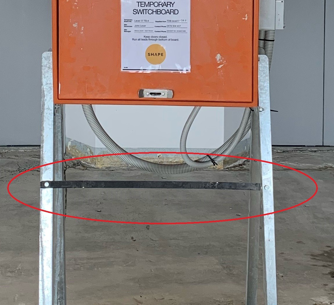
Switchboards are of robust construction and materials, to withstand mechanical damage from the environment or other external influences that may be expected at the location. In order of preference, this may include:
• Attachment to a wall, pole, post, floor or other stable structure
• Attachment to a freestanding or temporary structure, in an elevated position suitably designed for the purpose. It must be stable and the design must take into account any external forces that may be exerted on the board (e.g. bolted to the slab, fixed securely to the ground, or secured to a wide base of support)
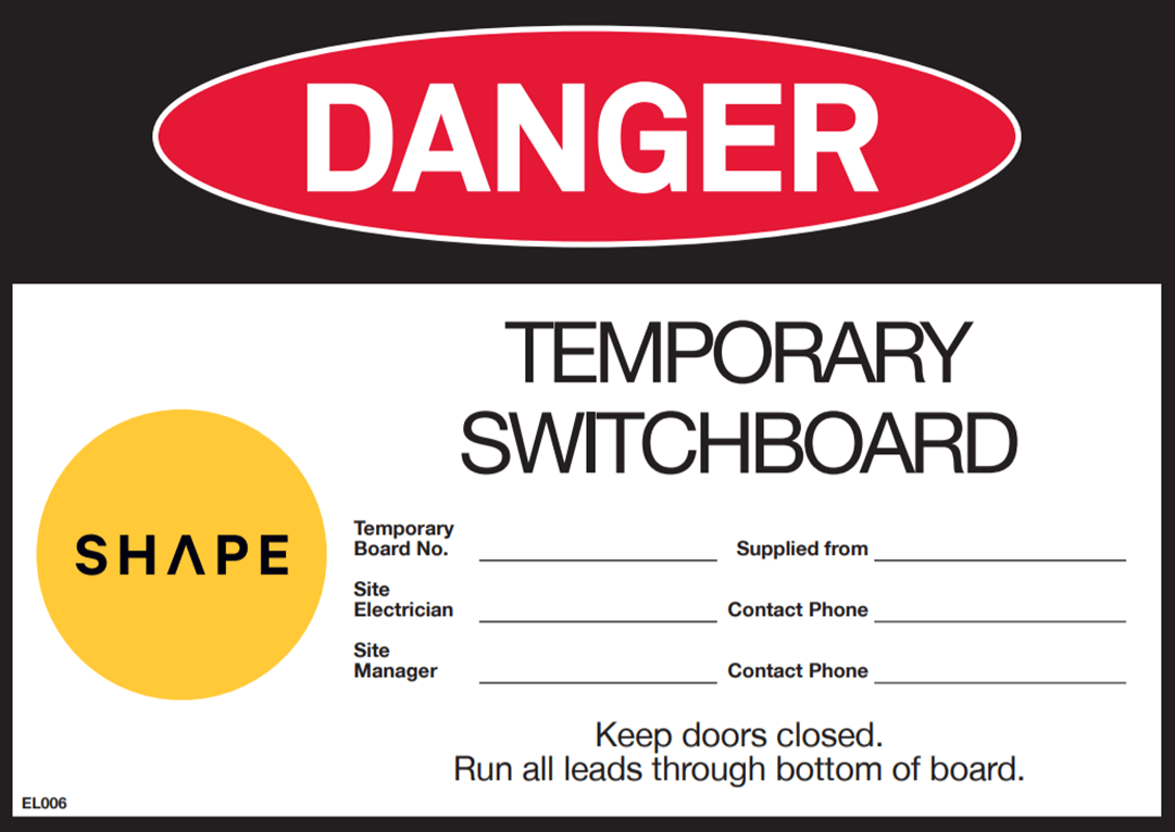
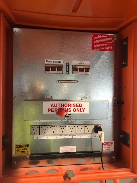
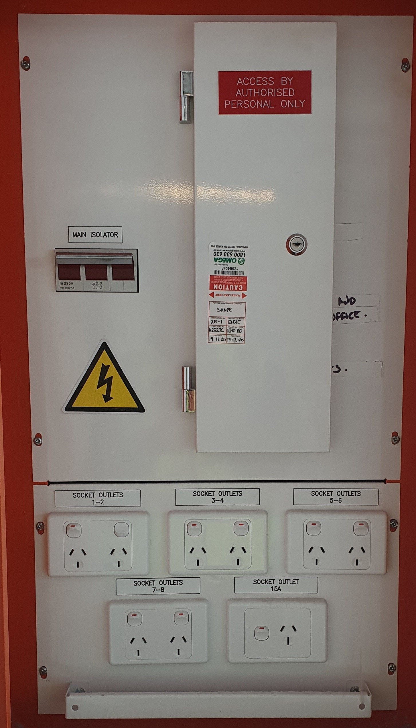
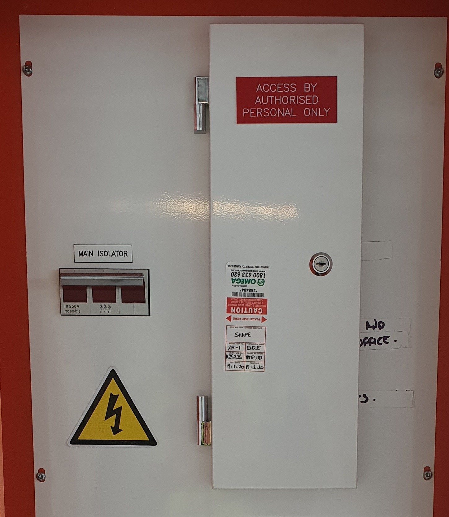
The SHAPE temporary switchboard signage is posted on the front door of all switchboards. This is to ensure that each switchboard identifies the source of supply from which it originates, and that each switchboard is marked by way of numbers, letters, or both to distinguish one switchboard from another.
In multi-level buildings, switchboards are positioned in a manner that eliminates the need for flexible cords or cables to be run between levels (exceptions for work in lift shafts, stairwells, service shafts, formwork, external staging or sub-mains of construction wiring).
For outdoor locations and areas susceptible to moisture, switchboard enclosures have a minimum degree of protection of International Protection (IP) rating 23.
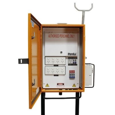
Live parts are effectively protected at all times against contact by people operating equipment on the switchboard, including the connection or disconnection of plugs to socket outlets (i.e. escutcheon panels are secured and all pole fillers are in place).
An insulated tie-bar or similar arrangement is in place on each switchboard for the anchorage of cables or flexible cords, in order to prevent strain and mechanical damage at their connections or terminations.
An insulated lead support is provided directly above the board, at a minimum of 2.2m above the floor level.
Each switchboard has a door or lid to maintain a degree of protection. The door or lid:
• Requires the use of a tool for removal
• Is fitted with a facility for locking
• Is fitted with a means of retaining the door in the open position, when the board is in use
• Is kept closed except when access is required
• Allows the safe entry of leads away from pinching points in the door, to prevent damage to the leads
• Has words to the effect of “Keep Doors Closed. Run all leads through bottom of board.”
The “live parts” or “electric shock” symbol is displayed in locations where additional attention is required to be given to the removal of covers and the like (i.e. as a minimum on the escutcheon panel).
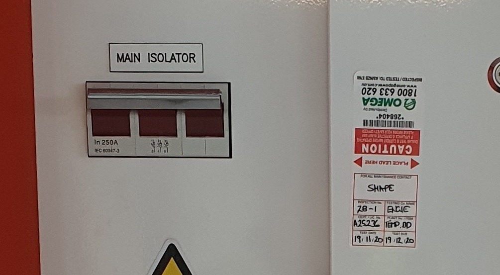
All switchboards are provided with a clearly labelled main isolating switch, which interrupts supply to all final subcircuits, submains and socket outlets originating from the board.
When the isolating switch has been activated, provision must be made to prevent electrical equipment from being inadvertently energised, i.e. deliberate action in addition to the normal method of operation is required to energise the circuit. This provision may be via the locking of the switchboard door, or another lockable space or enclosure. Warning tags or notices alone are not acceptable. Short-circuiting and earthing may only be used in addition to locking.
Lockable covers are fitted over RCDs associated with outgoing circuits. These covers must not prevent access to the isolating switches. This is not a mandatory legal requirement in all states however SHAPE adopts this well known practice as a national minimum standard.
All cable entry ports are insulated to protect cables from damage.
A person has been nominated to ensure that all power circuits are isolated or made inaccessible so as to eliminate the risk of fire, electric shock or other injury to persons after completion of the daily work.
All temporary supply mains are protected by a circuit breaker or high rupturing capacity (HRC) fuses.
Switchboards display only current testing information, i.e. all out of date test labels have been removed.
Switchboards are supplied via new cable runs.
Note: this means that existing cables may not be used to supply temporary switchboards or lighting.
Submains cables supplying temporary switchboards are physically protected in conduit from the board and into the ceiling space or beyond if the works activities in the location present a risk of damaging the cable.


Battery charging tables have been provided to the side of, or behind switchboards.
Auxillary socket-outlet panels meet the requirements of AS/NZS 3012 Section 2.6.11. Of note, they must be:
• Located at a height of between 1.2 and 2m above the floor
• Securely mounted to a permanent structure or a temporary structure that has been specifically designed for the purpose
• Must be individually controlled by a double pole switch
Portable RCD boxes (Portable Socket-Outlet Assemblies or PSOAs) must meet the requirements of AS/NZS 3012 Section 2.6.10. Of note, they must:
• incorporate over-current and RCD protection
• be of robust construction
• have extended sides or covers over the outlets
• have a degree of protection appropriate for the environment (IP33 as a minimum)
• incorporate a heavy duty flexible cord no more than two metres long
Domestic type powerboards, double adaptors, three pin plug (piggy back) adaptors and homemade powerboards must not be used on construction or demolition sites.
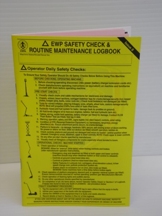
EWPs are mobile platforms that lift or lower people or equipment from a base support using either a hinged, articulated or combination (hinged and articulated) device. Types of EWPs include scissor lifts, self-propelled boom lifts, trailer or vehicle mounted lifts and telehandlers with elevating work platform attachments. Construction work using EWPs is high risk construction work.
During preconstruction, the project team reviews the scope of works with respect to Elevating Work Platforms for inclusion into the Project Risk Register and Project Delivery Plan.
The site’s designated loading / unloading area has been assessed for overhead services, weather conditions, lighting, traffic routes (both internal and external to site), eliminating the risk of collision with other people or plant, and the ground has been assessed by a structural engineer or geotechnical engineer (when required) to ensure it is adequate to support the EWP and its transport vehicle
Contractor Safe Work Method Statements (SWMS) are prepared by subcontractors for construction work associated with EWPs, and reviewed using the SWMS Review.
The selected EWP is the most appropriate plant or equipment to perform the work task, and the SWMS or methodology elaborate on appropriate hazards and controls for the work, including but not limited to:
- structural failure, overturning, or collapse of the machine
- contact or collision of the EWP with people, plant and structures leading to crush injuries and entrapment
- inadequate ventilation in the area the EWP is used
- restricted working space, and
- falling objects and falls from heights.
Alternative access methods, such as scaffolding, have been considered to reach and carry out the task prior to the decision to use an EWP
The contractor’s site-specific SWMS or methodology considers the hazards and controls regarding the delivery and collection of EWPs, i.e.:
- Transport operators are trained and competent in how to operate the EWP, how to use the loading equipment and load restraining equipment, how to inspect load restraining equipment prior to use, emergency procedures for the type of plant, etc.
The site’s designated loading / unloading area is then prepared prior to the estimated arrival time of the EWP, including but not limited to traffic control, spotters and warning signage in accordance with the site Traffic Management Diagram
A Plant and Equipment Induction has been completed. Where required, the following documentation is reviewed and copies are maintained on site:
- The plant provider’s risk assessment
- The contractor’s SWMS related to the use of the plant, which includes site specific requirements
- Daily inspection logbooks
- Service records
- Operations manual
- Verification of operator competency
- Plant and Equipment Registration (in line with state and Territory regulatory authorities – refer to Item 3 of the Plant and Equipment SHAPE Minimum Standard)
- Registration with Road Authorities where the plant itself is to be driven on public roads
- SHAPE’s Plant Induction sticker may be used to easily identify inducted plant and reinspection timeframes
The Plant and Equipment Register is updated to include the EWP and associated records
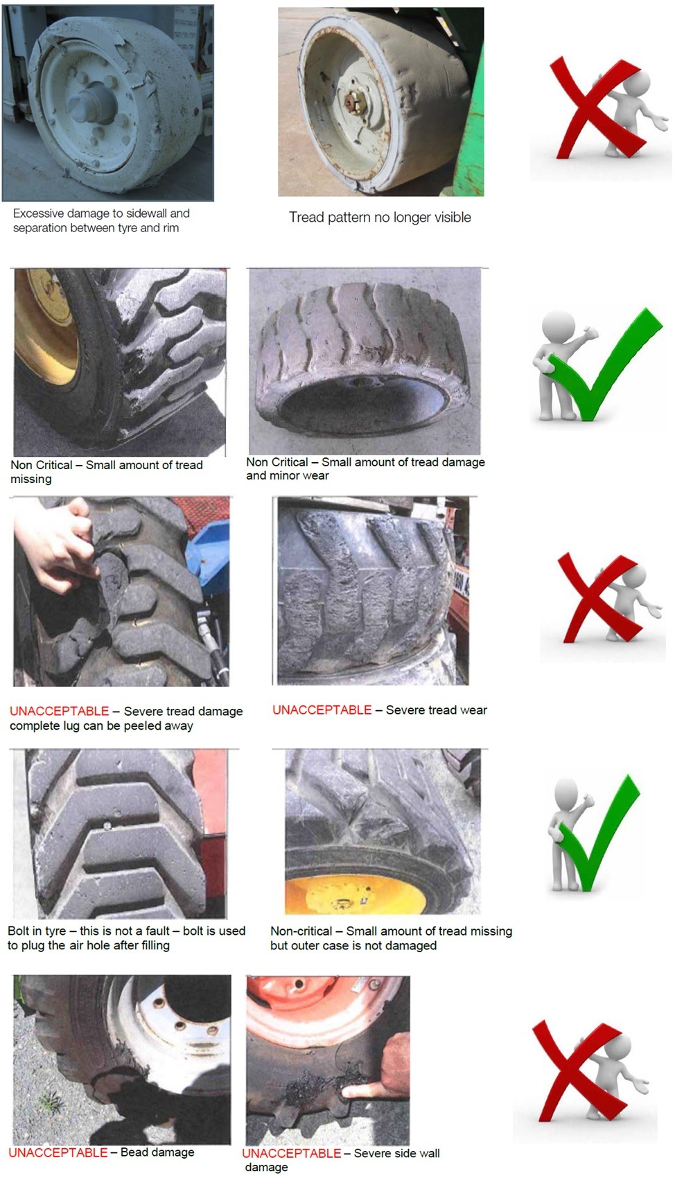
EWP tires are in good condition with minimal damage. Puncture proof tyres are used where the loss of inflation could cause instability
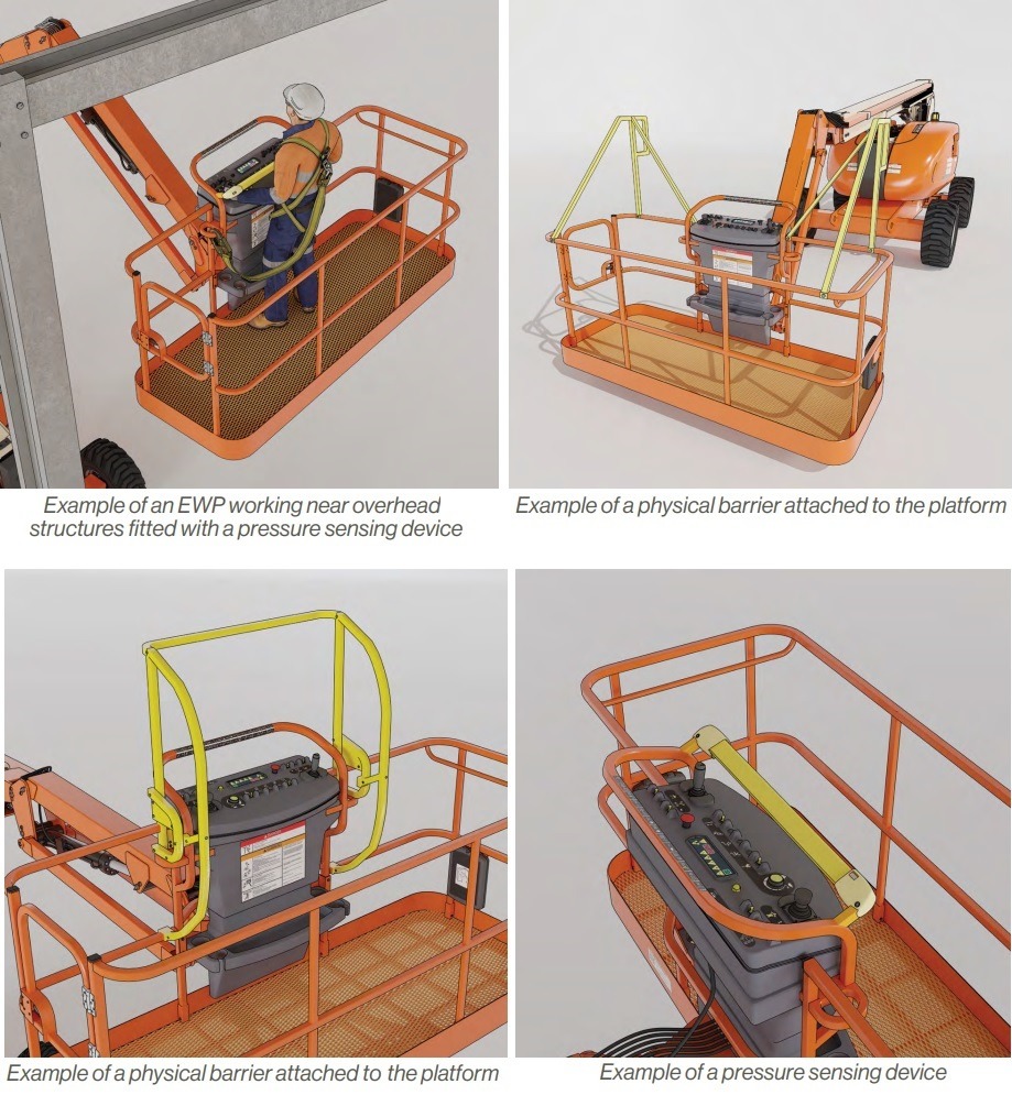
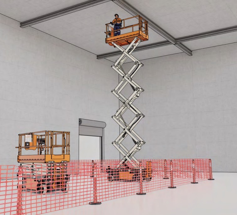
When there is a risk of crush injuries (i.e. when working near overhead structures or services), secondary guarding or protective devices are installed by the manufacturer / supplier.
Such devices may include:
- physical barriers attached to the platform
- pressure sensing devices positioned over the control panel, which detect pending crush incidents and prevent further hazardous movements
- proximity sensing devices which prevent an EWP’s platform from manoeuvring into high-risk areas near to fixed structures
The operator’s competency has been verified in relation to the selected type of EWP, and a photocopy is taken and kept in the site files, i.e.:
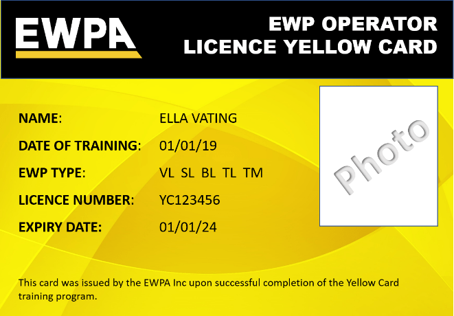
- To operate a scissor lift (SL) or vertical lift (VL) of any platform height, there is no requirement to hold a High Risk Work License however operators need to demonstrate that they have been trained in and are familiar with the equipment they are operating. This training can be obtained by undertaking an EWPA Yellow Card course;
- The High Risk Work Licence for boom-type elevating work platforms is not evidence of competency to operate a scissor lift or vertical lift – you must be trained and familiar with scissor lift operation before you can use it;
- To operate a boom-type Elevating Work Platform where the length of the boom is under 11m, evidence of training can also be obtained by undertaking the EWPA Yellow Card course;
- To operate a boom-type Elevating Work Platform where the length of the boom is 11m or more, a High Risk Work License for Boom-type elevating work platforms (code WP) is required
Relevant information, training, and instructions have been provided to workers who are involved in the activity. For example: the Site Induction, Toolbox Talk, training in the SWMS, Pre-Start Meeting.
Overhead and underground services (such as gas, water, fire services, overhead power lines and electrical cables) have been identified through review of As-Builts, Dial-Before-You-Dig and scanning techniques. Relevant asset owners are identified so that they can be consulted in planning for the works
Due to the importance of a prompt rescue, EWP operators should never operate alone in the event they become sick, injured, stranded, suspended or trapped at height due to malfunction or misuse of the EWP.
Support personnel need to maintain line of sight to the operator and should not leave the area until the EWP is lowered to a stowed position and the operator has alighted from the platform.
For scissor lifts less than 11m, as a minimum the EWP Emergency Response Plan is completed by the scissor lift operators and ground-based support / emergency response personnel prior to works commencing.
For all other types of EWPs (i.e. scissor lifts greater than 11m and all boom-type EWPs), in addition to being trained in the EWP Emergency Response Plan the ground support personnel must also:
- be licensed to operate the type of plant they are spotting, with evidence of this competency copied and retained in the site files; OR
- be a trained Dogman / Rigger, with evidence of this competency copied and retained in the site files
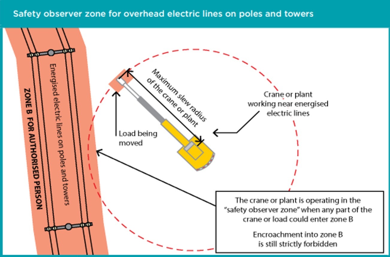
On SHAPE workplaces an EWP should never be used in the vicinity of live overhead electrical lines.
If this situation is ever to occur, a detailed SWMS, Emergency Response Plan (which includes provisions for a trained LV rescue person with an LV rescue kit to monitor the activity), and Electrical Deviation Risk Assessment must be endorsed by the relevant SHAPE state General Manager or delegate prior to works commencing.
One spotter will be required for each item of plant or equipment operating in the vicinity of overhead electrical lines. Spotter competencies must be copied and retained in the site files, and must include:
- The license / competency to operate the type of EWP (or Dogman / Rigger competency)
- A current competency to ‘Provide First Aid’ (HLTAID003) or equivalent
- A current competency to ‘Provide Cardiopulmonary Resuscitation’ (HLTAID001) or equivalent
- (In Victoria only) an approved Spotter training course (22325VIC) (Course in Workplace Spotting for Service Assets) and hold a current Spotters Registration Certificate/Card which is valid for a period of three (3) years
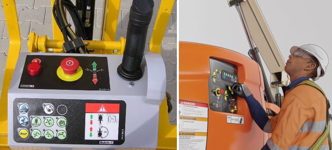
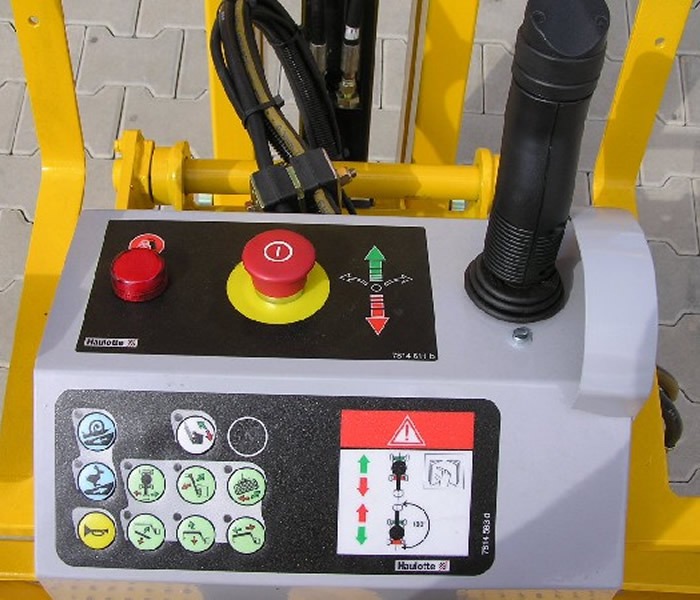
Emergency controls are clearly visible, known by operators and spotters, and are accessible at all times during operation of the EWP
Attachments fitted to EWPs to hold material have been installed as per the manufacturer’s instructions by a competent person (such as a fitter or mechanic) and have been inspected and approved by an engineer or workplace safety regulator
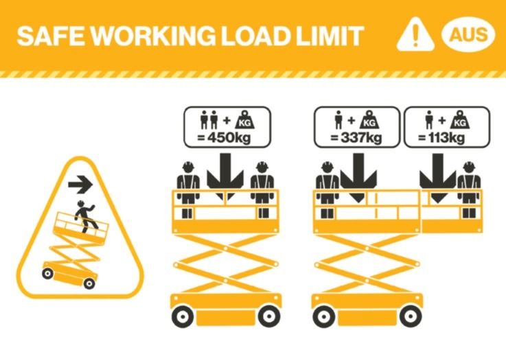
Safe working loads are displayed on the EWP and are understood by the operator and passengers
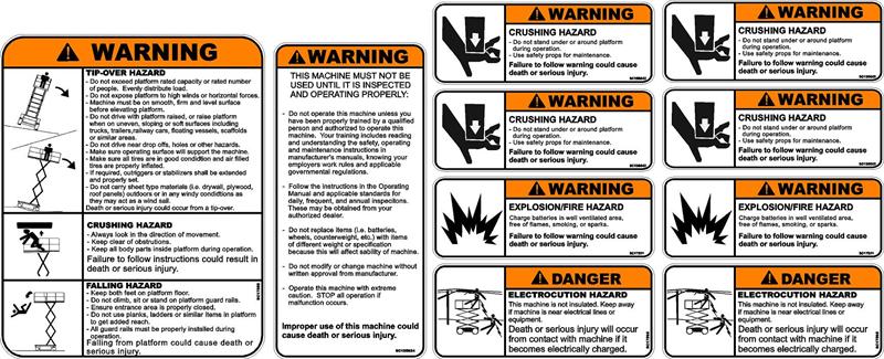
Permanently fixed and legible operating instructions (decals) are displayed at operating positions, i.e. at the ground controls, or cabin and basket controls
Exclusion zones and warning signage are in place to control plant, equipment, and worker interaction
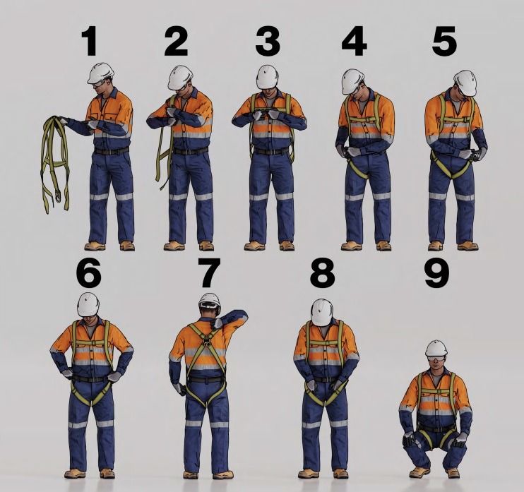
A full body safety harness is worn by every person on the platform of a boom-type EWP or vertical mast EWP fitted with a jib. This is to help control the risk of:
- a fall from the platform, should the platform strike an object
- a fall from the platform, should the EWP platform levelling system fail, resulting in the platform tilting or inverting
- a person being catapulted out of the EWP, for example while travelling over uneven ground or over a terrain drop-off
A full body safety harness is generally not required for occupants of scissor-type EWPs because they are protected by the guard rail on all sides of the platform. A fully body safety harness should be worn for scissor-type EWPs when recommended by the manufacturer or otherwise indicated in the site-specific risk assessment.
For relatively low height tasks, a site specific assessment is conducted to identify whether there is inadequate fall clearance, i.e. the potential for the fall arrest system (including energy absorber) to deploy and the occupant to still impact the ground.
If such a situation could occur, other methods for working at height such as using a mobile scaffold should be considered as a safer method for undertaking the task.
When a safety harness system is required, it complies with the AS/NZS 1891 Industrial fall arrest systems and devices series. When selecting lanyard lengths everyone on the platform should ensure that:
- the length of the lanyard is as short as possible, while still permitting the occupants in the EWP freedom of movement
- the operator is able to maintain both feet on the platform floor
Every person using a harness is competent in how to inspect, wear, use and secure a harness in accordance with the manufacturer’s instructions. Demonstration of this competency is provided (and a copy kept in the site files), and may include RTO training in Working at Heights RIIWHS204E, or a documented training record provided by the employer (if this training is delivered by a competent person).
Harnesses are inspected for defects prior to and after each use.
All personal equipment (including harnesses and associated equipment) are routinely inspected by a suitably competent person at six-monthly intervals.
Any harnesses that present with any defects are immediately removed from service, e.g.:
- Webbing: cuts, tears, scratching, grazing, excessive stretching, deterioration, rotting, mildew, Ultraviolet damage, heat damage (e.g. due to welding), exposure to corrosives or solvents
- Stitching: any fraying, cuts or tears which indicate potentially weak or damaged threads
- Snap hooks: hook or latch distortion (e.g. bending), cracks or forging folds, excessive wear at swivels or the latch pivot pin, open rollers, excessive movement of the latch, any broken, out of place or missing latch springs, soil or grime build up
- Buckles and adjusters: cracks, corrosion or other physical damage, missing parts, incorrect functioning, bent tongues, open rollers
- D-Rings: excessive movement of the D-Ring, cracks, signs of excessive wear, other physical damage
- Energy Absorber: signs of activation, tampering or damage
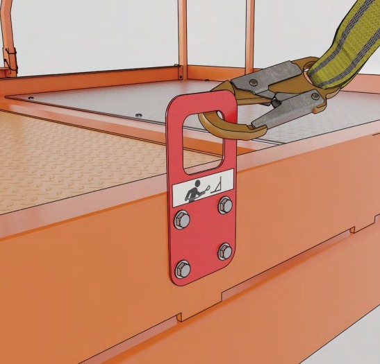
When a safety harness is required, a suitable anchor point is used such as the permanently fixed EWP anchor point
The surface incline is not exceeded with respect to the manufacturer’s operating instructions for that type of EWP
EWP movements only take place with the basket or work platform in the lowest position.
When movements are permitted by the manufacturer in the extended position, this may only take place in a designated exclusion zone and with spotters to eliminate the risk of collision with other plant, people and objects.
EWPs are not used as a material hoist. Materials to be installed that are with the worker in the EWP basket should fit inside the confines of the platform and still facilitate access, emergency egress and not compromise the operation of the controls.
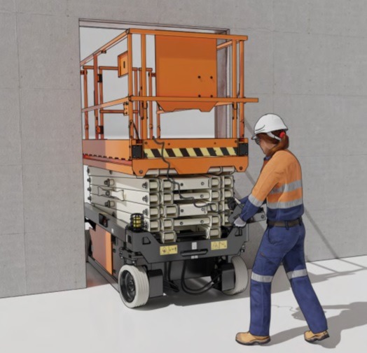
If an EWP is to be moved through a doorway or restricted opening, the operator will exit the basket and operate controls from the ground, moving the EWP from outside of the work platform.
A safety observer will be used on the other side of the doorway to alert people to stay clear of the EWP
Firefighting equipment is available within EWP baskets/cabins where hot works are being performed, and at the completion of works a 30 minute firewatch is completed and verified on the Hot Work Permit.
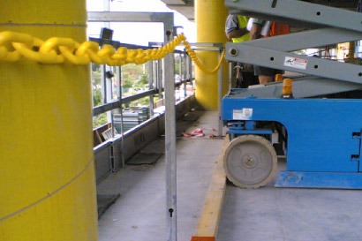
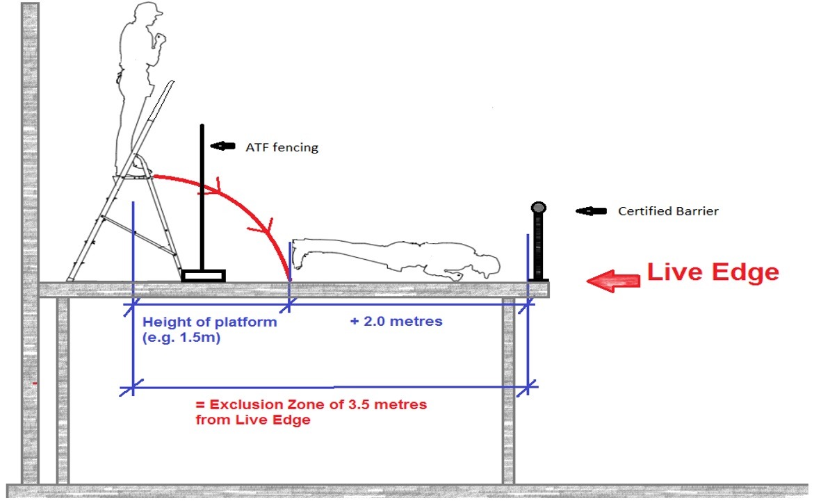
When EWPs are being used in the vicinity of a live edge (e.g. stair penetrations, kerb and channel, external building perimeters, change of levels), controls are in place to keep the EWP a safe distance from the edge, i.e. wheel stops, tethering, certified barriers.
Battery powered EWPs are recharged in a designated area located away from temporary construction switchboards.
The floor or ground load-bearing capacity have been verified in writing by a structural engineer (or geotechnical engineer where appropriate), and EWPs are parked for charging with a separation distance that avoids overloading the ground support structures.
Combustion type engines are only operated outdoors.
If operation of a combustion engine EWP is required in an enclosed or internal environment, adequate mechanical ventilation and air exchange must be implemented and monitored through consultation with a licensed Occupational Hygienist.
Refuelling of combustion engine EWPs is performed in a designated refuelling area. The work method is clearly addressed within the contractor’s SWMS.
An SDS for the fuel is provided to the SHAPE Project Team, and the product is entered into the Hazardous Chemicals Register after the completion of a Hazardous Chemical Risk Assessment which is signed by all workers involved in the refuelling works.
Suitable spill kits are located at the refuelling zone.
Emergency Preparedness and Incident Response planning is essential to ensure that all SHAPE projects and offices are adequately prepared and resourced in case of an emergency or in case any workers require rescue.
During pre-construction, the project team reviews emergency planning and incident response requirements for inclusion into the project Risk Register and Project Delivery Plan.
NB: this will include the Building Management Emergency Response protocols.
Projects with a higher risk profile are encouraged to use the separate Project Emergency Response Plan to sufficiently address the higher legal requirements for emergency preparedness (e.g. the use of Tower Cranes or mast climbers, cladding replacement works, where there is a risk of worker suspension at height, difficult or restricted access and egress situations, multi-level or spur / hung / cantilevered modular scaffolds, use of forklifts, civil works with the risk of powered mobile plant rollover).
The project’s designated emergency personnel are inducted into the site-specific emergency response procedures / plans by signing either the Project Delivery Plan or Project Emergency Response Plan, as appropriate
The nearest available health or medical services have been identified,and they have been contacted to establish their ability to assess or treat work-related injuries.
NB:
- Isolated sites (more than 20 minutes from appropriate medical services) may require further due diligence and planning to respond to medical emergencies
- For shift work, consideration must be given to the medical facility’s opening hours
Emergency Evacuation Diagrams have been created using the Evacuation Diagram Tool.
Emergency Evacuation Diagrams are displayed on site, in accordance with the Guide to the Evacuation Diagram Tool.
Emergency response procedures are documented to all workers and visitors within the Site Induction.
Emergency Evacuation training is completed within the first 2 weeks of commencing the project, and then every 3 months thereafter.
Task-specific Emergency Response Plans are prepared and implemented for all high risk activities or activities requiring potential rescue resources and equipment.
The nominated warden has completed a relevant training course through a Registered Training Organisation (RTO).
Risk Assessment of the project emergency response hazards within the Project Risk Register will determine the site’s firefighting equipment requirements, for example:
- Low Risk Environments – retain the existing base building equipment, OR provide at least 1 Class A (General) and 1 Class E (Electrical) extinguisher per floor
- Medium to High Risk Environments – provide 1 extinguisher for each temporary construction switchboard on site, i.e. if there are 5 temporary construction switchboards per floor then there should be 5 extinguishers per floor – the class/size of extinguishers required will be determined via risk assessment in consideration of the nature of work and combustibles on site
Note: it is not ideal to position fire extinguishers at/on Electrical Switchboards themselves – ideally they should be positioned in a highly visible and accessible standalone location
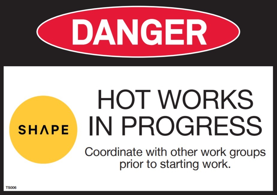
- Hot Works – A separate portable fire extinguisher of the appropriate class/size (provided by the subcontractor) is required in the vicinity of all hot works
Note: it is not ideal to position fire extinguishers at/on Oxy-Acetylene trolleys themselves when the Oxy-Acetylene kit is in use
Where hot works activities are undertaken, nominated personnel are competent in the use of fire fighting equipment. The nominated person has demonstrated that they understand how to select and use the designated fire fighting equipment.
Nominated first aid officers have current qualifications
First aid requirements for the project have been assessed by a qualified First Aider, are documented within the Project Risk Register and Project Delivery Plan, and are based on site-specific risks including the scope of works, environment and location. This risk assessment is developed with reference to the relevant state/territory First Aid Compliance Code or Code of Practice. Where the use of hazardous chemicals is required, additional first aid supplies may need to be provided by SHAPE or the subcontractor.
A First Aid Room is provided for sites that will reach a peak of 100 workers or more. The following items are provided inside the First Aid Room:
- A sink and wash basin with hot and cold water (unless this can be provided within easy access from the First Aid room)
- A work bench or dressing trolley
- Cupboards for storing medicaments, dressings and linen
- A hazardous waste container or bio-hazard bags for soiled dressing
- A sharps disposal system
- Electric power points
- Hygienic hand cleanser and disposable paper towels
- An examination couch with waterproof surface, pillow, blanket and disposable sheets
- An upright chair
- An examination lamp with magnifier
- A bowl or bucket (minimum 2 Litres capacity)
- A chair and a table or desk
- Names and contact details of first aiders and emergency organisations on the SHAPE First Aid contacts poster
- A first aid kit appropriate for the workplace, including a resuscitation mask and face googles
- A stretcher
- An Automated External Defibrillator (also known as an AED or simply a “defibrillator”)
A first aid room should:
- Be located within easy access to toilet facilities and a sink with hot and cold water (where this is not provided in the room itself)
- Offer privacy via screening or a door which remains easily accessible to emergency services, with a minimum door width of 1 metre for stretcher or wheelchair access
- Be well lit and ventilated
- Be large enough for its purpose (e.g. 14 square metres as a guide)
- Have an entrance that is clearly marked with the SHAPE First Aid contacts poster

Arrangements have been made to ensure first aid kits are regularly re-stocked.
Emergency Exits are clearly signposted and operational.
Where there are any changes to emergency exit requirements, these are communicated through a Toolbox Talk and the Site Induction.
Emergency Evacuation Diagrams are updated to reflect these changes.
Any action to the smoke detection, sprinkler, hydrant or fire hose reel systems that will be affected throughout the project have been communicated to all parties on the project via Toolbox Talk and Site Induction.
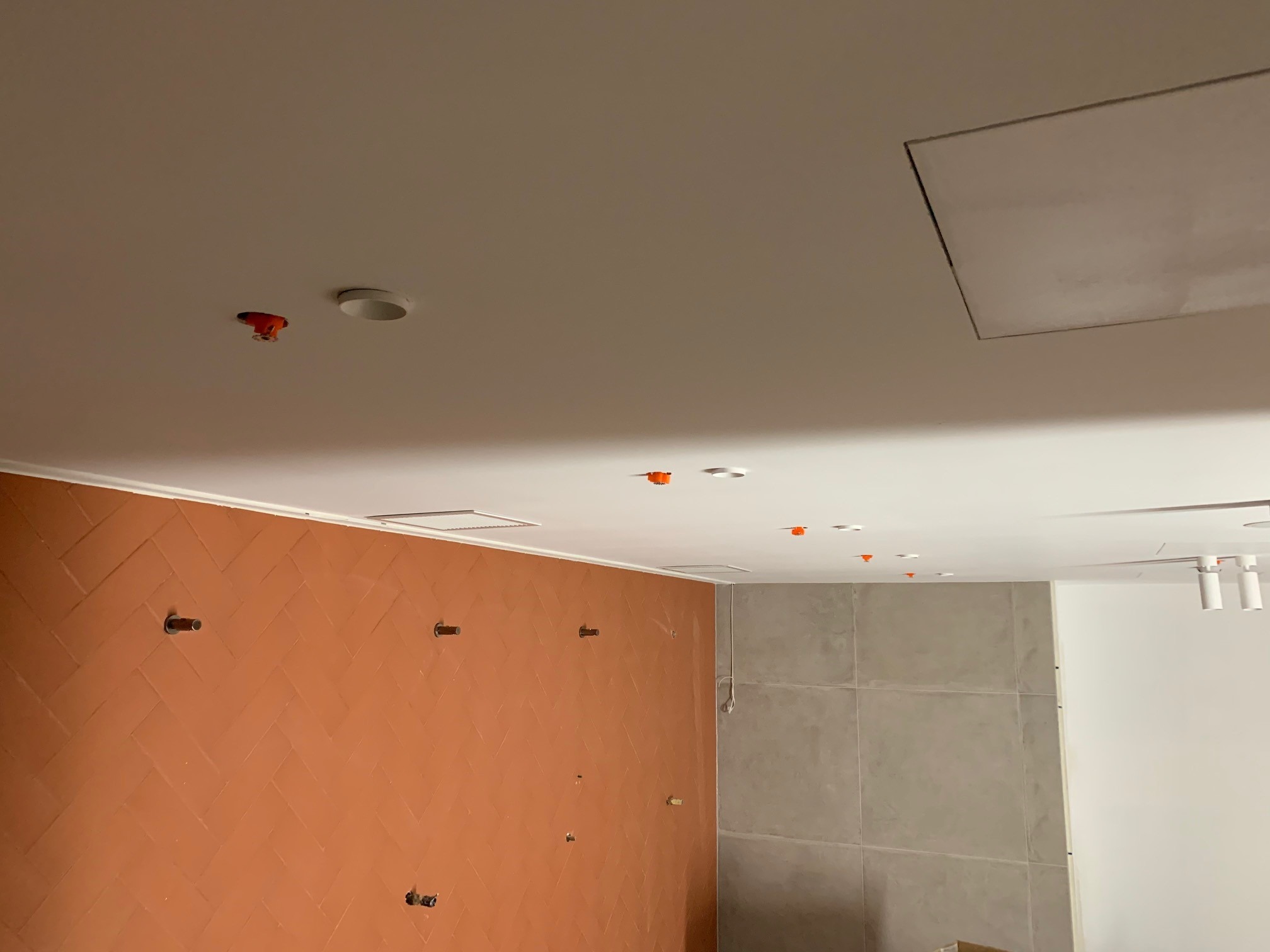
Sprinkler heads remaining active have been highlighted to improve visibility. Sprinkler heads at risk of damage have been capped or caged.
Control measures to manage damage to sprinkler heads have been risk assessed, with the controls implemented and communicated via Toolbox Talk and the Site Induction.
The building emergency warning system is operational throughout the project, OR an alternative warning system has been implemented (e.g. horn system, nurse call, etc.)
Risk Assessment of the project emergency response hazards (within the Project Risk Register and Project Delivery Plan), completed by a SHAPE Site Representative who has successfully completed a Fire Warder Training course through an RTO, will determine the site’s firefighting equipment requirements, for example:
- Low Risk Environments – Retain the existing base building equipment, OR provide at least 1 Class A (General) and 1 Class E (Electrical) extinguisher per floor
- Medium to High Risk Environments – Provide 1 extinguisher for each temporary construction switchboard on site, i.e. if there are 5 temporary switchboards per floor then there would be 5 extinguishers per floor – the class/size of extinguishers required will be determined via risk assessment in consideration of the nature of work and combustibles on site (note – it is not ideal to position fire extinguishers at or on Electrical Switchboards themselves – ideally they should be positioned in a highly visible/accessible standalone location)
- Hot Works – A separate portable fire extinguisher of the appropriate class/size (provided by the subcontractor) is required in the vicinity of all hot works (note – it is not ideal to position fire extinguishers at or on an oxy-acetylene trolley when that oxy-acetylene kit is in use)
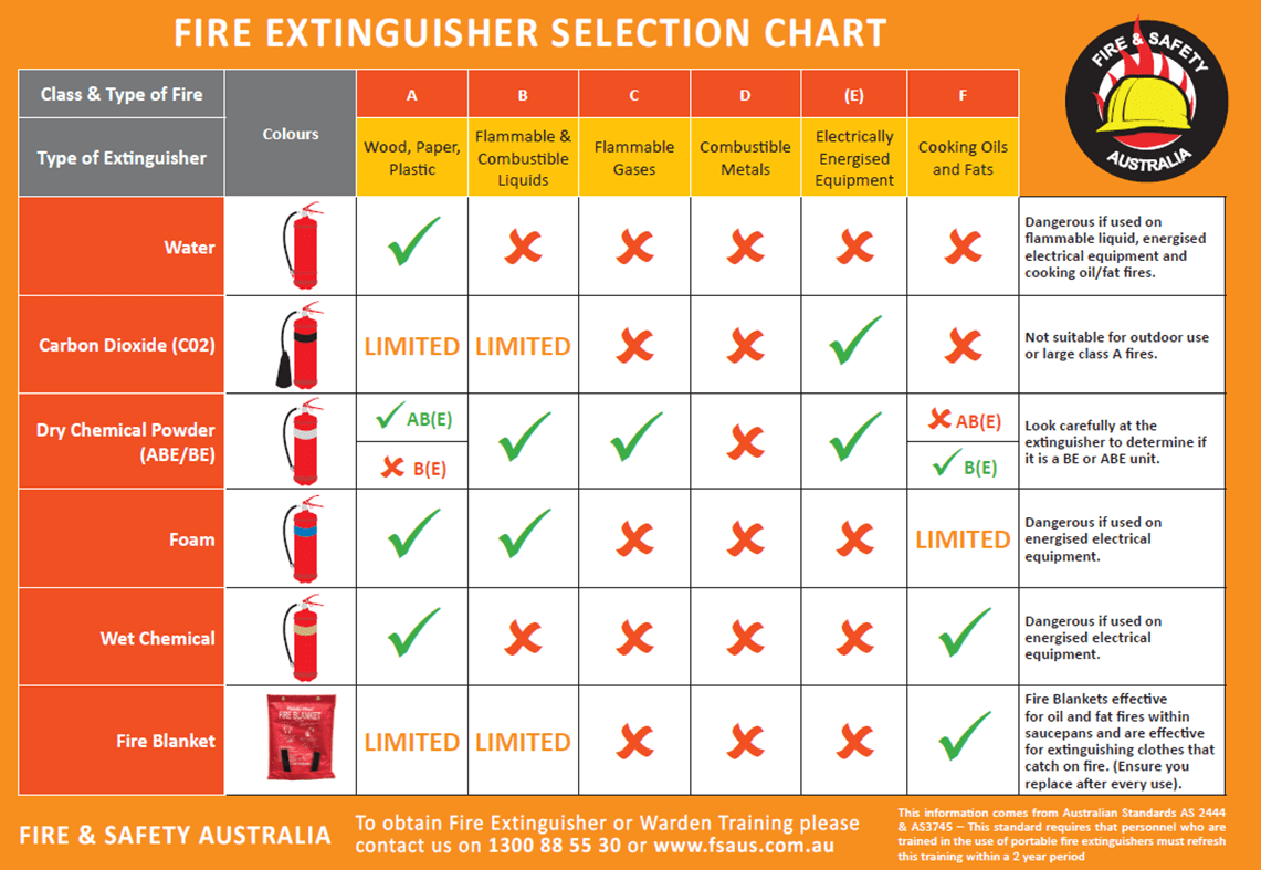
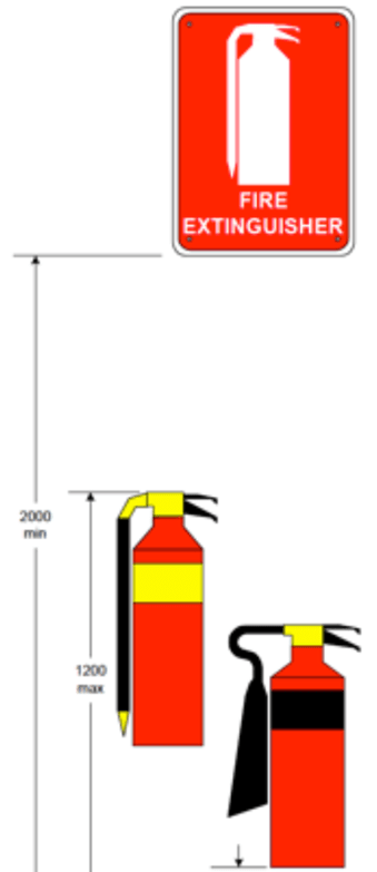
Fire extinguishers and their signs are mounted in accordance with AS2444. This includes, but is not limited to:
EXTINGUISHER MOUNTING WALL BRACKET HEIGHTS
- A minimum of 100mm from the floor to the bottom of the extinguisher (fire extinguishers must not be situated on the ground)
- A maximum of 1200mm from the floor to the top of the extinguisher handle
LOCATION AND DISPLAY OF SIGN
- Minimum of 2000mm above floor level
- At a point that makes them most apparent to a person of average height & visual acuity
- The extinguisher or extinguisher sign shall be clearly visible for up to 20 metres on approach
- The size of the sign shall be determined by location on and distance at which the sign must be legible
- A minimum of one Pictorial or location sign must be provided above or adjacent to an extinguisher, even if indicating the location of multiple or a mixed group of extinguishers
- The extinguisher and fire point location signs shall have a symbol, border and letters in white on a red field, complying with Australian Standard (AS) 2700
- Australian Standard (AS) 2444 Portable Fire Extinguishers and Fire Blankets – Selection and Location provides comprehensive and specific information
- It is also recommended that you have a square instruction disc (ID – SIGN) directly above the extinguisher wall bracket. Even though these details are on the portable fire extinguisher they can get covered up with stickers, etc. blocking the instructions
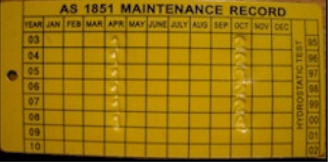
Firefighting equipment is within test date.
Q: How do I understand the tag? A numeric symbol is marked in the month and year for each inspection and certification.
Q: What do the numeric symbols stand for?
1 – six monthly inspection
2 – yearly inspection
3 – (this numeric symbol is no longer used, the previous Australian Standard has been superseded)
4 – five yearly inspection (pressure testing)
5 – after use service
Should a critical incident occur, all SHAPE project stakeholders and senior leadership team members review and implement their actions and communication protocols as outlined in the Critical Incident Response guide.
SHAPE is committed to promote sustainability as an integral part of each project, to encourage better environmental practices among the suppliers and subcontractors we engage, and establish measurable objectives and targets that address our environmental impact.
During pre-construction, the project team reviews the scope of works with respect to environmental aspects and impacts for inclusion into the Project Risk Register and Project Delivery Plan.
The project Site Induction includes environmental controls specific to the project:
- Spill control
- MDF cutting
- Ventilation – natural or mechanical
- Dust/sediment suppression
- Stormwater management
- Waste water management
- Noisy works
- Hazardous Chemicals (refer to the Hazardous Chemicals SMS)
- Waste Management
- Flora and fauna
Subcontractor SWMS include environmental aspects, impacts and control measures, including requirements for the handling, storage, use and disposal of Hazardous Chemicals in accordance with the SDS.
Spill kits are:
- Fully stocked
- Appropriate for the scope of works
- Positioned in the area of risk
- Sign posted
Workers are aware of spill control measures, as outlined in the product’s SDS.
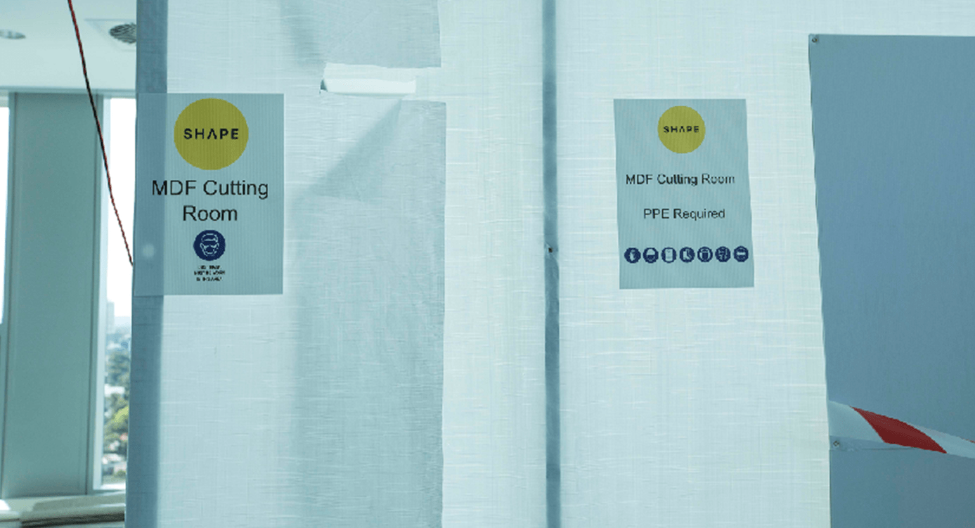
MDF cutting:
- Wherever possible, alternative products to MDF are to be used (e.g. Emissions Zero or EO board, Hoop Pine)
- If MDF is to be used, MDF cutting is to be completed off site wherever possible
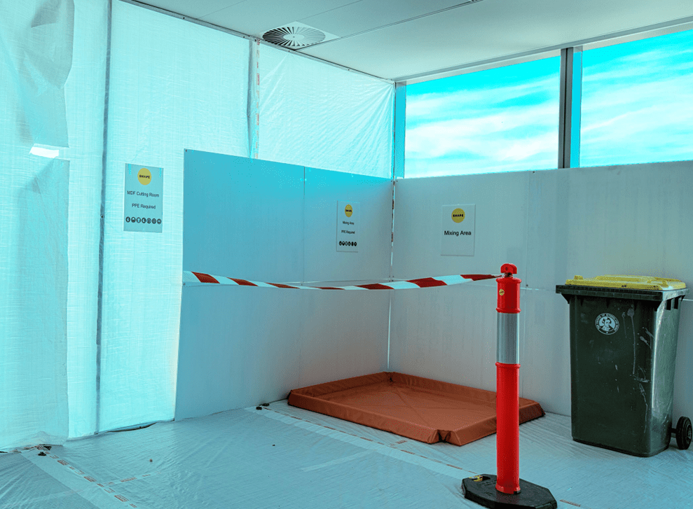
- If MDF is to be cut or sanded on site, an MDF cutting room has been established in accordance with the Medium Density Fibreboard (MDF) Procedure.
- MDF cutting rooms are identified with the following signage at the entrance:
- MDF Cutting Room warning signage
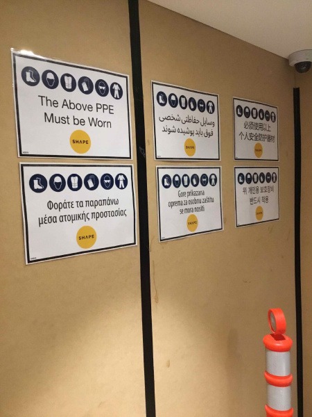
- Mandatory PPE signage
- Workers are to wear PPE in accordance with the product SDS
- Cutting tools will be fitted with a HEPA-vacuum extraction system
- The room is kept tidy at all times, and dust is bagged for disposal
Ventilation:
- Where natural ventilation is not adequate for the site, mechanical ventilation is used, e.g. extraction fans, pedestal fans, portable air conditioning units, etc.
- Where existing mechanical services are operational, additional filter media will be installed over air intakes to prevent contamination
All activities that may cause dust or release airborne fibres have control measures in place to prevent contamination of common air spaces, impacts on other trades and offsite impacts.
Dry sweeping is not permitted on SHAPE sites.
Dust controls may include:
- Water suppression
- Negative pressure air zones
- Use of extraction systems with in-built filtration
- Tool accessories
- Wet brooming
- Vacuum equipment
- Limiting the use of exhaust emitting equipment
- Banning excessively smoky vehicles and equipment
- Enclosed areas for dedicated dust generating activities
- Air quality monitoring
- Conducting work out of normal hours
- Encapsulation or treatment of exposed synthetic mineral fibre

For external works:
- Water trucks
- Hydroseeding / spraygrass
- Stockpile encapsulation
- Rumble grids / shakedown tracks are in place for vehicle access and egress
- A road maintenance cleaning program is in place (e.g. street sweepers or similar)

Consideration is given to the potential introduction of contaminated soils, fill and mulch products (which are often man-made products constructed from recycled or waste material). Examples of possible contamination include asbestos, lead, PFOS/PFAS, acid sulphates, other chemicals, fire ants, plastics, glass, etc.
Soil, fill and mulch products are only procured from reputable suppliers, the materials are visually inspected upon delivery for any signs of visible contamination, and if in doubt project teams will consult with an Occupational Hygienist to determine a suitable and site-specific inspection and sampling process.
Note: for schools and public infrastructure projects, always seek proportionate sampling and testing processes from an Occupational Hygienist as the material arrives to site.
Stormwater management controls are implemented when appropriate:
- Filtration media
- Filtration socks
- Hay bales
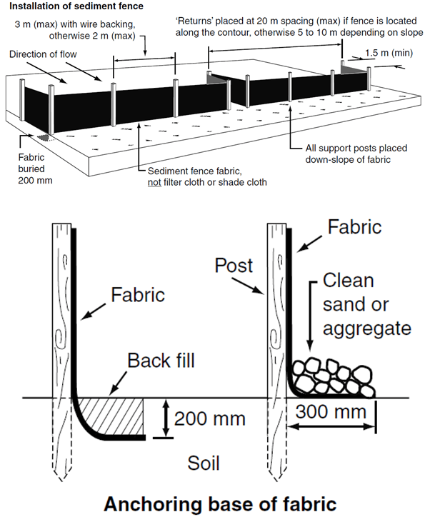
- Silt barriers/fences
- Tarping of waste containers or stockpiles in adverse weather conditions
Waste water management controls are implemented when appropriate:
- Designated and bunded wet trade mixing areas
- Wash out systems (e.g. Dulux Envirowash System, Resene WashWise, or similar)
- Sediment tanks (e.g. for plaster, cement, tiling products, etc.)
- Waste water is disposed of in accordance with the SDS, and local council or Environmental Authority requirements


Noisy works controls are implemented when appropriate:
- Work methods are selected which eliminate or minimise noise generation as much as practical (e.g. placing materials instead of dropping, exhaust silencers are used, sound rated rooms, use of acoustic panelling and other noise dampening materials, cutting rooms, etc.)
- Plant and Equipment are turned off when not in use
- Works are in accordance with building management and Development Approval (DA) constraints
- Noisy works are scheduled at a time that reduces exposure to other workers
- Where possible, workers are excluded from noisy work locations
- Neighbours and stakeholders are notified in advance of planned noisy works activities
- Hearing protection must be worn by workers and others in the vicinity of the noise
- Noise monitoring and assessment is conducted for repetitive noisy works
Monitoring and inspections take place via site walks and Procore Hazard Observations
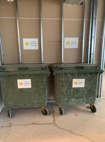
Waste management controls are in place and effective:
- Waste management strategies are communicated as part of the Site Induction
- There is an adequate number of bins
- The size and type of bins are appropriate for the type of waste generated by the scope of works
- Bins are not overflowing
- There is a bin exchange or turnover strategy in place, which is communicated at induction
- A waste tracking and separation plan is in place (NB this is mandatory for all Green Star projects)
- A housekeeping strategy is in place
Paint and/or hazardous products are appropriately managed (i.e. storage, signage, handling and disposal are in accordance with the SDS).
Posters or signage highlighting environmental initiatives (e.g. recycling) are displayed on site.
Vehicle movements and parking are managed to minimise environmental impact on the neighbourhood and other stakeholders.
Sediment fencing is in place where required
Flora and fauna controls are implemented when appropriate:
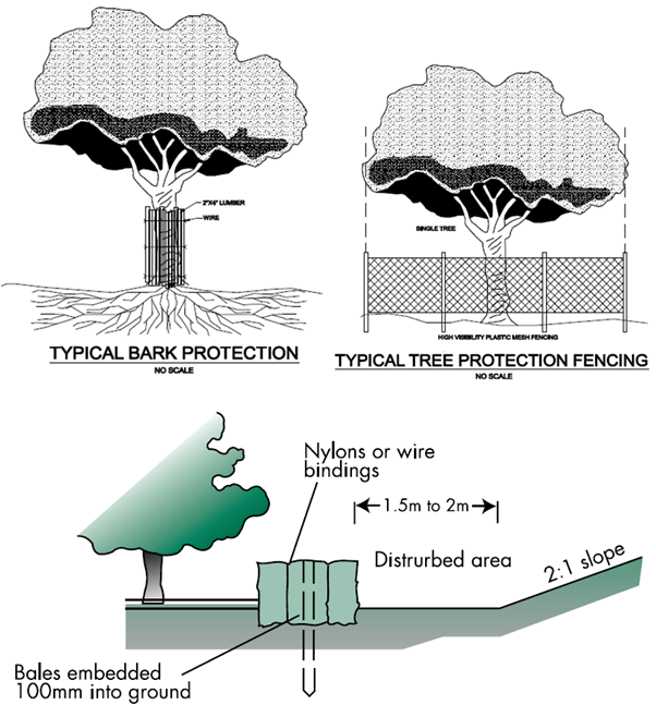
- Garden beds are protected
- Trees are adequately protected
The intent of this SMS is to provide management and control guidelines for Excavation and Trenching activities.
During pre-construction, the project team reviews the scope of works with respect to excavation and trenching work for inclusion into the Project Risk Register and Project Delivery Plan.
Contractor Safe Work Method Statements (SWMS) are prepared by subcontractors for construction work associated with work in and around a trench or excavation and reviewed using the SWMS Review. SWMS must detail hazards and controls associated with an excavated depth greater than 1.5 metres and/or the risk of a person falling more than 2 metres.
The earthmoving plant selected is suitable for the work being performed, including consideration of the materials, load, frequency, proximity of other plant/structures.
A competent person has conducted a documented inspection / risk assessment of the excavation site prior to starting work.
Soil type information must be provided by a geotechnical engineer for trenches and excavations 1.5m or greater in depth and for any excavation in unstable soil.
Before excavating check the geotechnical soil report for acid sulphate soils and your jurisdiction’s “EPA Contaminated Sites Register” for the site location and classification – additional risk management may be required.
If acid sulphate soils are present or the site is classified as contaminated, consult with an occupational hygienist regarding state and local government requirements / Australian Standards for sampling and testing, excavation, remediation and soil removal requirements.
If after review of soil reports, EPA Contaminated Sites Register and other relevant project documentation there is no evidence of soil contamination or special conditions in relation to soil management, where possible a review of the site’s previous uses (i.e. industrial, commercial, domestic, etc.) should be undertaken in conjunction with a visual inspection of the site by an occupational hygienist.
If following review there is no reason or further evidence to suspect soil contamination – excavation may commence without further testing or sampling in accordance with all other relevant aspects of this SHAPE Minimum Standard and the spoil may be disposed of to an off-site facility.
NB – prior to soil leaving any site, check with the nominated off-site disposal facility for any other specific soil classification / management requirements.
If at any time during excavation activities there is reason to suspect previously unidentified soil contamination – stop work immediately and engage an occupational hygienist to complete an investigation and report.
Relevant information, training, and instructions have been provided to workers who are involved in the activity. For example; Site Induction, Toolbox Talks, training in SWMS, Pre-Start Meetings, etc.
For all excavation activities on public or private land, Before You Dig Australia (BYDA) must be contacted.
Note: Before You Dig Australia (BYDA), formerly known as Dial Before You Dig, provides the free pre-excavation referral service for the Australian community. BYDA provides a single point of contact to request information about any infrastructure networks at the planned project site.
The relevant regulators, asset owners or other external authorities have been notified of works (e.g. when excavating contaminated soil, working near overhead power lines or working near assets owned by other stakeholders) and their approval has been received prior to commencing excavation.
Information about underground services is communicated to workers involved in the excavation work – including when it is not in the immediate vicinity. Where this is risk of damage to services, alternative excavation methods should be considered (e.g. hydro or vacuum excavation).

An adequate consultation / communication process must be conducted with all relevant parties prior to the excavation work commencing.
Where the excavation is located near other plant or structures, control measures are in place to prevent injury to workers and members of public.
Following the Planning and Risk Assessment of Trenching and excavation activities an Excavation Permit must be completed and issued to the subcontractor directly involved with the works prior to work commencing.
When the cutting or coring of concrete is required prior to the excavating, the Cutting and Coring Concrete and Masonry Elements Procedure is implemented.
Ground penetrating radar (GPR) scanning is completed prior to commencing excavations – Include visual inspections of areas to be excavated for tell-tale signs of underground services such as sunken trench lines, service pits, and surface mounted lighting poles, above ground electrical pillars.
Appropriate exclusion zones and warning signs are established around excavations and plant and equipment paths of travel.
When ground support systems are used (such as benching, battering or shoring), a documented safe system of work (SWMS) is in place to minimise the risk of injury to people during installation, use and removal of the system.
A documented inspection on the benching, battering, shoring or other ground support system is performed by either the system designer or a qualified engineer experienced in excavation temporary works, to ensure the system is installed in accordance with relevant legislation, codes of practice and Australian standards, manufacturer’s requirements and where applicable the drawing / plan:
- Before it is relied upon by workers; AND
- At a minimum, once every 30 days; AND
- After any significant weather event, repair, modification, alteration or incident which may affect the integrity of the system
Records of these inspection and maintenance activities are kept on site.
Shorter inspection intervals (i.e. more frequently than every 30 days) may be appropriate depending on the size of the ground support system, workplace conditions, weather conditions, or any other factors that could affect the stability of the system – the ground support system designer / engineer is to provide this advice when relevant.
Ground support systems are inspected to monitor the effectiveness of the system in accordance with relevant legislation, codes of practice and Australian standards, manufacturer’s requirements and where applicable the drawing / plan:
- Daily (i.e. before each entry shift), with any required corrective or preventative actions to be documented in the Daily Pre-Start Meeting, with this inspection performed by a person trained in either:
- RIICCM210E – Install Trench Support (or equivalent); OR
- The manufacturer’s specific ground support system installation requirements
- Weekly inspections are performed by SHAPE Project Team members using the Procore Benching, Battering, Shoring or Other Ground Support Systems Inspection
The risk of people falling into the excavation has been adequately controlled through use of barriers – this should include provisions to prevent unauthorised access afterhours. Certified barriers are required where work is in the immediate vicinity of the live edge.
A safe means of access and egress from the trench or excavation has been provided.
The risk of people being struck by falling objects must be adequately controlled.
All additional task and site specific hazards or risks associated with the excavation work must be adequately managed. This has been addressed in the Project Risk Register and communicated through the Site Induction.
Monitoring of trenching an excavation activities is completed via the Task Inspection. The presence of asbestos must also be considered in areas known to have been filled or past building sites.
Construction work involves a number of high risk activities and the use of potentially dangerous plant and equipment, which if operated while fatigued can result in serious injury or even death. The following Minimum Standards are provided to ensure the safety of everyone impacted by our construction work - including ourselves, our co-workers, clients, tenants and the general public.
During pre-construction, the project team reviews the scope of works with respect to the potential impact of fatigue for inclusion into the Project Risk Register and Project Delivery Plan.
In the development of the Project Delivery Plan, project teams are to agree on standard working hours, conditions and timeframes that are appropriate for the project and client, contractors and SHAPE workers themselves.
Risk assess project resourcing requirements regularly depending on the nature and scope of current works.
Coordinate trades to schedule similar out of hours works together (e.g. core holing activities), rather than on multiple separate occasions.
When planning for out of hours works, consideration should be given to avoiding high risk activities in the closing hours of the shift. Workers are generally more alert and focused at the start of the shift and better equipped to follow instructions and make sound decisions.
Proactively discuss and manage fatigue with the workforce, particularly after emergency events or significant incidents have occurred which may result in workers working longer shifts – ensure supervisors manage this proactively with their resourcing.
When appropriate, communication to subcontractors about management of fatigue with their workers is documented in an email and records of this communication are retained.
Ensure fatigue is included in your subcontractor’s SWMS, particularly for safety critical activities.
Ensure that all workers on the construction site (including subcontractors) have been given the site specific induction, and made aware of the requirements of the Project Delivery Plan.
Provide adequate facilities for rest breaks (e.g. lunch room, amenities).
Incident Reports should be raised for instances where fatigued workers have been identified on site, or particularly where there was potential for workers performing high risk work (safety critical activities) also being fatigued.
The erection, use and dismantling of formwork and falsework is high risk work. Formwork is the surface of the form and framing used to contain and shape wet concrete until it is self-supporting. Falsework is the temporary structure used to support a permanent structure, material, plant, equipment and people until the construction of the permanent structure has advanced to the stage where it is self-supporting.
During pre-construction, the project team reviews the scope of work involving the erection of formwork, falsework, propping and placement of concrete and stripping for inclusion in the Project Risk Register and Project Delivery Plan.
All formwork systems are designed by a suitably qualified and competent engineer (e.g. a structural engineer, or a civil engineer experienced in structural design).
Design of all formwork systems, both traditional and modular, meet the requirements of AS 3610 Formwork for Concrete and AS 3600 Concrete Structures, and considers:
- The type of formwork such as conventional or proprietary systems
- Components to be used e.g. size and shape
- Configuration of the system
- Conditions of the site, e.g. ground conditions prevailing weather
- Stability of formwork during erection, pouring and dismantling
- Using off-site construction methods such as concrete girders lifted into place in lieu of in-situ form
- Minimisation of working at heights
- Fall protection provisions
- Guiderails
- Sloping surfaces on formwork
- Manual handling
Design safety reports have been received and recommendations have been included into the Project Risk Register and Project Delivery Plan. They are then distributed to the formwork contractor for inclusion into their safe system of work.
Systems of work developed by the formwork contractor are clear and always in accordance with the formwork design.
The formwork contractor’s systems of work are flexible enough to meet changing circumstances as the work progresses, provided such flexibility does not depart from the formwork design. The system of work provides for the assessment and control of any new risks arising from proposed changes to the work before they are implemented, i.e. RFIs are issued to the formwork designer when a potential conflict arises between the on-site installation and the documented design.
A documented safe system of work can be an administrative control that complements higher level controls. This could include the following:
- Communication and consultation
- A project risk assessment
- Safe Work Method Statements for high risk construction work
- Access and egress
- Exclusion zones
- Permit-to-work systems
- Fall arrest / restraint systems
- Inspection and maintenance
- Emergency evacuation arrangements
- Changes to the work arrangements
Prior to commencing formwork operations, the following steps have been carried out:
- Site-specific Safe Work Method Statements have been reviewed and in place
- Suitable access in and out of the formwork zone is in place for workers and mobile plant
- The ground conditions where formwork is placed has been assessed by a competent person (e.g. a geotechnical engineer) and is adequate to support the weight of the formwork and concrete and any additional live loads such as pumps, workers, mixers, pouring of concrete and so on
- A structural engineer has provided confirmation that the structure, building connection points, foundations and materials are adequate
- Weight distribution / load placement drawings and plans have been prepared based on the engineered design requirements
- Signage is prepared for installation on site to ensure the weight distribution / load placement requirements are complied with at all times – this information must also form part of the Site Induction content or a separate Toolbox Talk
- Unauthorised persons are prevented from entering the work area. This includes physical barriers and hazard warning signs clearly displayed around formwork activities to warn other persons/trades on site
- Electrical hazards (overhead and underground) has been identified and controlled
- Emergency response plans have been documented and tested
- All persons carrying out the work have received appropriate training, information and instruction
- All proprietary formwork components and formwork materials such as joists, bearers, plywood, support frames, jacks and U heads are used in accordance with manufacturer’s specifications
- Proprietary connecting devices and props pins are used. Improvised bolts and or reinforcing steel must not be used for this purpose.

Evidence of competency for formwork and falsework workers are copied and retained in the site files (i.e. Certificate III in Formwork / Falsework)
Emergency plans consider:
- The method for alerting workers in an emergency
- The method of extracting workers from each location or cell that people have entry to or could fall into
- When to evacuate workers from the form
- Evacuation muster points both on and off the form
- Location and use of fire extinguishers
- Identifying workers responsible for ensuring evacuation takes place
- Rescue procedures for severe medical conditions
- Damaged componentry/components
- Notifying emergency service organisations at the earliest opportunity
- Establishing communication protocols between relevant workers
- Testing emergency procedures for their effectiveness in dealing with an emergency
- Frequency of emergency drill testing
- Providing information, instruction and training to workers who may be affected by an emergency
Erection of formwork, falsework and propping is documented into a Safe Work Method Statement:
- Formwork frames are erected progressively to ensure the installers’ safety and the stability of the overall structure
- Bracing is progressively installed to provide reasonable fall protection during erection;
- Bracing is not used as final edge protection
- Where erecting the formwork requires people to stand at heights of two (2) metres or more above a level below, form workers can work within the formwork frame provided there is fall protection provided within the frame. An example of this would be to construct a temporary platform within the frame’s tower with the cross bracing or handrail installed to the sides enclosing the frame on four sides
- The false deck is constructed so there are no large gaps and gaps only exist where a vertical member of a frame passes through the deck. Gaps do not exceed 225mm in width
- Safe access is provided to each of the false decks

- Intermediate work decks are installed for erection of formwork above 4 meters above the below floor
- Where the potential fall distance is less than two metres, a catch platform or catch deck can be provided that is at least 450mmwide, which is not a working deck
- Bearers are placed on frames by workers off work platforms no more than 1800mm below them
- Bearers are held in place using U heads, the bearer is positioned in the centre of the U head

- U heads are rotated and fixed by nailing or wedging the bearer to prevent the bearer from moving off the centre of the U head. Where 2 bearers abut the U head does not need to be rotated
- Joints are installed to the bearer from below using a work deck progressively
- Formwork deck is laid in a progressive way so that workers will be provided with a method to prevent them from falling below the deck
- Workers start laying the form ply sheets from the perimeter scaffolding or other edge protection provided on the perimeter of the formwork
- A minimum of four joists at 450mm centres—400mm gaps, totalling 1.8 metres—are located on bearers next to the person and in the other direction joists extend for at least 1.8 metres. Therefore, if a person falls they will fall onto the joists and should be prevented from falling further
- Lower areas of the deck (beams or drop downs) are constructed first to minimise fall hazards from higher levels of the deck

- Leading edge hazards are documented in the formwork contractor’s SWMS
- Task Inspections are completed on all tasks undertaken by the formwork contractor
The Formwork, Falsework and Propping Inspection is completed prior to any loading or use as structural support, or prior to concrete pouring.
Formwork, falsework and back propping is inspected by a structural engineer to ensure it meets the design specification and is structurally sound before it is loaded with concrete. A pre pour certificate is issued by the structural engineer before loading with concrete.
Additional documented inspections on the formwork, falsework, propping and supporting structures are performed by the structural engineer at least once every 30 days, and after any significant weather event, repair, modification, alteration or incident which may affect the integrity of the structure.
Records of these inspection and maintenance activities are kept on site.
Building structures, materials, foundations and underground services will be assessed and controls will be in place prior to starting the design or installation of any other temporary structural support systems (that will be subject to loading or use as structural support). This is to ensure that structures, materials and foundations are able to carry and distribute all the weight of the temporary structural support system:
- Concrete slabs or other building elements that the temporary structural support systems are being erected on have had their bearing capacity assessed by a structural engineer or the structural support system designer
- Soil or other natural substrates that the temporary structural support systems are being erected on have had their bearing capacity assessed by a geotechnical engineer and this information has been provided to the structural support system designer.
Any temporary structural support systems that will be subject to loading or use as structural support will be:
- Designed by a suitably qualified and competent engineer (e.g. a structural engineer, or a civil engineer experienced in structural design)
- Documented on up-to-date drawings or plans
- Installed in accordance with the manufacturer’s instructions, relevant legislation, codes of practice and Australian Standards and the experienced subcontractor’s safe systems of work or SWMS
- Inspected by a structural engineer (or when appropriate, a representative of the contractor trained and experienced in inspecting and verifying the correct installation of the temporary structure), to ensure it meets the design specification and is structurally sound before it is loaded or used as a structural support
- Re-inspected as a minimum once every 30 days
- Re-inspected by the structural engineer (or the trained and experienced contractor representative, when appropriate) after any significant weather event, repair, modification, alteration, incident or change which may affect the integrity of the structural support system.
Records of all inspection and maintenance activities are kept on site.
Shorter inspection intervals (i.e. more frequently than every 30 days) may be appropriate depending on the size of the structural support system, workplace conditions, weather conditions, or any other factors that could affect the stability of the structural support system – the structural support system’s designer/engineer is to provide this advice when relevant.
Safe access and egress to the formwork has been provided and may include:
- Fit for purpose temporary ramps (cleated)
- Secured planks on top of steel reinforcement to provide safe access and egress from completed formwork decks
- Using the existing floor level of a building, where entry is safe
- Installing temporary stairs or portable ladder access systems for use when erecting the formwork and falsework
- Personnel hoists – non-mechanical forms of exit (e.g. a ladder or stair tower should also be provided in case of power failure or another emergency)
- Appropriate safe access to safely remove injured and ill workers
- Barriers are in place to prevent other trades such as steel fixers, plumbers and electricians from the formwork erection zone
- Formwork has been inspected and the work zone has been deemed safe for other trades

Controls for falling objects are in place such as:
- Overhead protective structures
- Perimeter protection screens
- Catch platforms
- Catch nets
- Exclusions zones below
Weight distribution / load placement drawings and plans have been prepared based on the engineered design requirements.
Signage is in place to communicate the engineered design requirements, including approved material set down areas, weight limits, weight distribution / load placement – this information must also form part of the Site Induction content or a separate Toolbox Talk.
The weight distribution / load placement requirements are complied with at all times:
- Materials are only stored in the designated material set down areas
- Stored material is not overloading the formwork
- Penetrations on the formwork deck are covered by fit for purpose material which is secured in position, clearly visible and identified. Alternatively, leading or perimeter edge protection is installed. All installations are performed in accordance with the manufacturer’s requirements, or where applicable the relevant drawing / plan, and are completed by a person who has undertaken documented training in the manufacturer’s requirements. A copy of this training is retained in the site files.
- Open penetrations like stairwells or access for services have proprietary guarding installed
- Penetrations in concrete slabs have cast-in-mesh as a back-up system
- The mesh is 50 x 50mm mesh size or smaller and made of material capable of withstanding the potential imposed loads. Where mesh or other physical fall protection material is to be provided for larger penetrations this should be included in the slab design specifications to ensure it can withstand potential loads including those applied by people, equipment and material
- Penetration covers using plywood material should be structurally graded and identified using a bright colour paint. The cover must be firmly secured to the concrete or formwork deck and designed for potential loads that may be applied
- Before stripping formwork, penetrations cast into the concrete are covered
- Joists placed up to the edge of the penetration are secured so the timbers cannot spread if a person falls on them
- Guardrails used for edge protection have been designed and engineered as edge protection systems in accordance with AS 4994: Temporary edge protection – general requirements
- Guardrails and handrails generally incorporate a top rail between 900mm and 1100mm above the working surface and also incorporate a mid-rail and a toe board (except where it may be impractical to do so) and alternative control measures, such as exclusion or ‘no go’ zones, to ensure no one is at risk of being hit by falling objects from the work above
- Fixings used to secure posts to the deck should be fit for purpose and take into account that it must be able to withstand the force of a worker falling into the rail
- The edge protection is installed in accordance with the manufacturer’s requirements, or where applicable the relevant drawing / plan, by a person who has completed documented training in the manufacturer’s requirements. A copy of this training is retained in the site files
- The edge protection installer provides SHAPE with written verification at handover, before workers are permitted to access the area. The handover information includes written verification that the guardrail system and supporting structure are structurally adequate (eg. verification by a suitably qualified engineer), and that the guardrail system has been installed in accordance with the supplier’s instructions

Perimeter protection screens are an effective means of edge protection on a completed formwork deck. Perimeter protection screens may be installed on the formwork as it is constructed, in which case the formwork must be designed to support the screens.
Perimeter protection screens are installed in accordance with the manufacturer’s requirements, or where applicable the relevant drawing / plan, by a person who has completed documented training in the manufacturer’s requirements. A copy of this training is retained in the site files.
Perimeter protection screens are assembled, installed, operated, inspected and re-inspected by the holder of a rigging high-risk work licence who has received training from the screen manufacturer/supplier. Inspections and re-inspections may also be performed by a structural engineer.
Perimeter screens:
- Extend at least 1000mm above the finished floor level
- Have the ability to support or contain imposed impact loads including building materials, equipment and waste materials
- Have resistance to wind loads on the supporting structure
- Are inspected at least once every 30 days, or after any modification, incident or adverse weather event occurs which may have affected the structural integrity of the screen
- Are resistant to chemical reactivity including flammability
- Are ventilated
- Allow light transmission
- Provide a degree of protection from rain or washing down operations
- Have a pattern and frequency of fixing points
- Have gaps between the screen and formwork or slab less than 50mm
- Where gaps exceed 50mm, additional temporary measures such as flaps and covers are used
- The formwork contractor has a monitoring regime of the formwork in place during concrete placement to check for potential failures or collapse and to check that formwork movement does not exceed the specifications
- There is a documented communication system in place to alert others of potential issues
- The formwork contractor has workers available to carry out any emergency adjustments or repairs
- Placement is stopped whilst repair or adjustments are carried out
- Pour rate of concrete does not exceed the calculated rate
- Hoists, pumps and other equipment required for the pour are not fixed to the formwork without approval by the structural engineer
- A documented back propping design is in place and approved by the structural engineer prior to stripping
- Written confirmation has been received prior to stripping that the structure is self-supporting and stripping can commence
- Concrete test results have been received verifying concrete meets the design specification
A written methodology is in place for the stripping of the formwork including:
- The number of people involved
- Establishment of exclusion zones
- The sequence of stripping activities – usually the reverse order of installation
- Cleaning and removal of nails and sharps
- Stacking of material
- Minimising damage to the components
- Identification of dedicated walkways
- Formwork components are not dropped or thrown from a building or structure
- Where back-propping is required
- How the structural members will remain in place and the type and layout of members that will replace the formwork system
- Other special requirements involved in the stripping or building process, e.g. checking of back-propping after post-tensioning
- Providing lighting for the work area and surroundings
- Maintaining housekeeping
The use of Hazardous Chemicals often occurs out of convenience rather than necessity – for the purpose of this SMS the emphasis should be on use of alternative, non-hazardous products wherever possible.
During pre-construction, the project team reviews the scope of works with respect to Hazardous Chemicals for inclusion into the Project Risk Register and Project Delivery Plan.
Safety Data Sheets, also known as SDS’s, are current (i.e. less than 5 years old), have an Australian emergency contact phone number listed, and are filed in a dedicated SDS folder which is kept next to the first aid kit.
Note: a hard copy of all SDSs must be kept near the first aid kit, even for non-hazardous chemicals, so that the SDSs remain accessible to workers or can be provided to a doctor in the event of exposure. The advantage of supplying an SDS even for a non-hazardous product is that it provides a clear assurance that the product is non-hazardous, rather than simply relying on the absence of warnings on the chemical packaging.
A site specific Hazardous Chemicals Register is maintained on site. Only chemicals classified as “hazardous” according to their SDS need to be entered into the Register.
The subcontractor has provided a Hazardous Chemical Risk Assessment for their proposed use of any hazardous chemical; OR the key SDS information (including precautionary statements, first aid measures, fire fighting measures, accidental release measures, PPE / exposure controls, handling and storage, disposal) are clearly detailed within their SWMS, a Toolbox Talk or a Pre-Start Meeting.
Whichever record of induction to the use of the hazardous chemical is selected, the document must be signed by all users of the hazardous chemical and the SHAPE Site Representative prior to permission being given to commence the use of the chemical.
All substances are clearly labelled and stored in their original containers.
Note: Decanting chemicals into smaller containers is only permitted under the conditions outlined in Safe Work Australia’s Code of Practice for the Labelling of Workplace Hazardous Chemicals.
Flammable chemicals are stored in a ventilated area and away from ignition sources, with the required emergency response equipment located within the area.
The required first aid facilities are available and have been assessed to provide first response in the event of an exposure.
The handling, storage, use and disposal of all Hazardous Chemicals is conducted in accordance with the SDS.
Adequate ventilation has been provided to avoid a concentration of fumes. This may involve:
- Windows and doors being opened where possible
- The introduction of mechanical ventilation or extraction
- Using the building extraction system
Note: concentration of fumes can affect not only workers but also building tenants, via contamination of the mechanical services system and/or air displacement through operational lift shafts. Extra caution must be taken when working on a multi-tenanted floor.
Consideration should be given to the use of Hazardous Chemicals out of hours to reduce the frequency of exposure for other workers and tenants.
Hot works are a regular activity on SHAPE projects. Planning of friction cutting, welding, brazing and other heat producing activities is essential.
During pre-construction, the project team reviews the scope of works with respect to hot works activities for inclusion the Project Risk Register and Project Delivery Plan.
The building management and tenancy fitout guide has also been reviewed to ensure the inclusion of building management requirements for hot works – i.e. impairment notices, building specific controls, notification periods, fire services isolation requirements, etc.
Following the development of the Project Risk Register and Project Delivery Plan all relevant information in relation to hot works is detailed within the project Site Induction.
Subcontractor SWMS are reviewed via the SWMS Review to ensure hot works activities, hazards and controls including emergency response plans have been addressed when appropriate.
Where hot works activities are undertaken, consideration should be given to work benches, waste bins, fire extinguishers, permit holders, brooms, dust pans, etc. which are negotiated with subcontractors.
Hot Work Permits are in use for any activity that may generate heat, fire, smoke, or if there is a risk of combustion.
Hot works are not performed outdoors / in open air on a Total Fire Ban Day, unless the relevant permit has been approved by the local authority.
On non-fire ban days, consideration is still to be given to weather conditions when completing external hot works.
Fire extinguishers and fire blankets must be provided by the subcontractor undertaking the hot works.
Fire extinguishers are suitable for the task being performed and located within the immediate vicinity of personnel performing hot work activities.
Note: when working at heights, the fire extinguisher must be located within the EWP basket or on the scaffold platform, etc.
Fire extinguishers are within test date (within 6 months of the last date stamp).
Base building or client fire extinguishers should not be used except in emergencies (e.g. not to be used by subcontractors for hot works activities).
Flashback arrestors are fitted to gas torch leads (both the regulator end and torch end).
Flashback arrestors on hoses have been installed, and have been tested or replaced at intervals of at least every 12 months.
Records of inspection or maintenance should be provided by the subcontractor when requested. One means of compliance may be to tag or attach stickers to oxy fuel gas equipment that has been inspected and tested.
Gas hoses and fittings are in good condition.
Welding equipment is in good working order.
Adequate ventilation is provided or is available for welding activities.
Welding screens are provided for Arc, MIG & TIG welding activities.
Warning signage is posted to advise others of potential hazards.
Areas below overhead welding / hot works are isolated with exclusion zones and signage.
Combustible material has been removed or is protected from hot work.
Protection measures are in place to prevent sparks or debris entering public areas.
Where hot works are undertaken via height access equipment (e.g. EWPs), consideration has been given to protecting internal components from heat affected falling debris which may ignite an equipment fire.
A minimum 30 minute fire watch is coordinated for all hot work activities.
Note: some clients may require a longer duration fire watch as part of their own, or building management requirements.
Cylinders are stored in accordance with manufacture requirements, if overnight then correct storage in an approved cage has been allocated space on the project.
The storage of gas cylinders on site should be limited to those cylinders in active use, rather than bulk-storage. i.e. there is a regular exchange program in place.
Note: empty gas cylinders should be removed from site within 24 hours.
PPE is being used in accordance with controls listed in the contractor’s SWMS & the Hot Work Permit.
Suitable respiratory protection for each welding task is risk assessed, selected and documented prior to works commencing. This risk assessment should consider the duration of the activity, location of existing ventilation, etc.
Refer to the Hot Works Procedure for further guidance.
Lasers are commonly used for alignment, levelling, control and survey tasks for construction work. Each state’s health and safety Regulations impose certain requirements in relation to the safe use of laser equipment at the workplace.
During pre-construction, the project team reviews the scope of works with respect to the use of lasers for inclusion into the Project Risk Register and Project Delivery Plan.
Qualified and trained personnel are assigned to install, adjust and operate the laser equipment. This person is also responsible for the implementation of laser safety controls. Verify competency via Certificate of Competency, related trade or industry qualification.
Appropriate laser warning signs are posted in areas in which these lasers are used.
Precautions are taken to ensure that persons do not look directly into the beam, e.g. placement of the laser at floor level or above ceiling level.
Precautions are taken to ensure that the beam is not viewed directly through optical instruments.
Appropriate eye protection is worn, e.g. specific laser safety eyewear.
The laser beam is terminated at the end of its useful beam path.
Precautions are taken to ensure that the laser beam is not unintentionally directed at mirror-like or specular surfaces (especially flat or concave mirror-like surfaces).
The equipment is being used in accordance with manufacturer’s instructions and contractor’s Safe Work Method Statement (SWMS). This is assessed through the Task Inspection.
When not in use, is the laser equipment stored in a location where unauthorised persons cannot gain access.
Class 3B and Class 4 lasers are not used without completion of a project specific risk assessment, which involves the SHAPE EHSQ team.
Detailed planning for Lifting Operations will ensure worker safety and deliver project quality and efficiency outcomes.
During pre-construction, the project team reviews the scope of works with respect to lifting operations for inclusion into the Project Risk Register and Project Delivery Plan.
Permits have been applied for through the relevant councils, police and road & traffic authorities.
A competent person has determined the type of crane to be suitable for the lifting work to be performed.
A SWMS (including a documented emergency response plan) has been received and the SWMS Review has been completed.
A reliable method of communication between the crane operator and dogger(s) has been documented in the SWMS.
Comprehensive documented lifting procedures (which may be referred to as “Lift Plans”) are required in the following situations:
- Tilt-up panel jobs
- Multiple crane lifts, where more than one crane is used to lift a load at any one time
- Lifting of workboxes with people in the boxes
- Installation of bridge beams during bridge installation work
- Working near live overhead powerlines
- Lifting large pressure vessels or tanks
- The use of mobile cranes on barges
- Erection of tower cranes
- Heavy lifts where the load is 50 tonnes or more
Documented lifting procedures (“Lift Plans”) for the lift types mentioned above should include the following:
- Maximum load radius to be used for the cranes
- Where spotter duties are required (e.g. for preventing collision or contact with powerlines), what the duty is and who is responsible for performing the duty
- Position of the load to be lifted and the final position to which it is to be lifted, where practicable (a diagram that shows a plan view of the site may assist)
- Maximum wind speed where the load has a large surface area
- Verification of the maximum allowable ground bearing pressure (this must be carried out for heavy lifts that involve tilt-up panels, bridge beams or any load weighing 50 tonnes or more)
- Allowance for any factors that may require de-rating of the crane (e.g. for multiple crane lifts, additional radius caused by tilting of tilt-up panels)
- Rigging requirements of the job
Any workbox being used to lift people must be designed and constructed according to Australian Standard 1418.17 and 2550.1, and be certified as fit for purpose.
Work boxes must:
- Be design registered with the state or territory regulator
- Have the working load limit (WLL), tare mass and design registration number clearly marked (no less than 25 mm high and in a colour contrasting with the background), e.g. on a data plate
- Have sides not less than 1 metre high
- Have fall-arrest anchorage points
- Be correctly tagged
- Have lifting slings supplied to be attached to the lifting points by hammerlocks or moused shackles
- Have a safety factor for each suspension sling of at least eight for chains and 10 for wire rope
- Where provided, a door is to be inward opening only and self-closing with a latch to prevent unintentional opening
- First aid boxes may be provided with outward opening doors for ease of access, but doors are to be self-closing with automatic latches
When using a crane-lifted work box or a first aid box, the crane itself must:
- Have a rated capacity of at least twice the total load of the workbox and its contents, at the maximum radius for the task to be performed and not less than 1000 kilograms
- Be fitted with an upper hoist limit that stops operation of the hoist and luff functions of the crane
- Have levers and foot pedals that are fitted with a constant pressure system that stops the crane’s motions when the operator removes pressure from the controls
- Not be capable of free fall
Refer to the relevant state, territory or Safe Work Australia Information Sheets for further requirements relating to crane lifting people in workboxes.
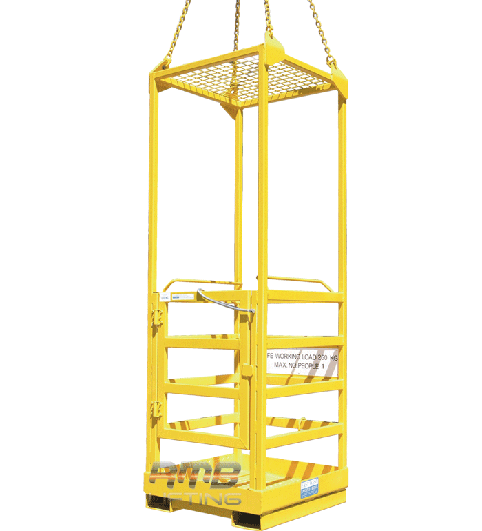
Relevant information, training, and instructions have been provided to all workers who are involved in the activity. For example: Site Induction, Record of Toolbox Talk – High Risk Activity Emergency Response, training in the company’s SWMS, Pre-Start Meeting.
The annual inspection is current, and a record is kept on file.
If the crane is ten years or older, the major inspection certificate is available for inspection and is kept on file.
The Plant and Equipment Induction been completed.
Crane Operators involved hold the required high-risk work licence for the class of crane being used. Copies of high risk work licences are kept on file.
Dogmen and Riggers involved hold the required high-risk work licence. Copies of the licences are kept on file.
Lifting procedures and plans define responsibility and approach the crane lift in a logical, systematic way.
“Special“ lifts should have an Independent Third Party Review by a specialist consultant with expertise in lifting operations. Definitions of “Special” may vary however the following is suggested as a basis for discussion:
- If one or more of the following criteria are triggered (via a Risk Assessment) then the lift should be classified as Special:
- Two or more cranes being used simultaneously to lift or lower loads
- Heavy or irregular load
- High crane usage factor (i.e. greater than 80% of rated capacity)
- Poor information on load weight distribution or Centre of Gravity (CoG)
- Poor information on lift points
- Complex or non-determinate rigging, particularly where the system relies on length adjustment devices to work such as chain blocks
- Poor or unusual ground, subsurface services. High Bearing Pressure under outriggers (i.e. greater than 20 tonnes per square metre (200 kPa))
- Other risk factors as determined by SHAPE
Special lifting arrangements are documented within a task-specific methodology
The crane operator manual and crane load chart are available in the cab and written in English.
Factors have been considered that could affect the ability of the ground to provide adequate support (e.g. underground services, trenches, excavations, pits, tanks).
Where hazards have been identified in the above item, certification has been provided by a competent person that the surface has adequate bearing capacity to support the crane (e.g. structural engineer, geotech engineer, scanning techniques).
When a crane is positioned near a trench, the nearest outrigger to the trench must be at least as far away from the trench, as the trench is deep. This rule assumes a zone of influence working at a 45° angle.
Assessment of the size and complexity of the lifts has been completed to determine resourcing. The Subcontractors involved have confirmed that adequate resourcing will be provided.
A Lifting Operations Permit has been issued.
The operator has carried out a documented pre-operational inspection on the crane prior to starting the day’s work.
Public and site Traffic Management Plans are implemented for all movements of the crane, e.g. exclusion zones, barriers, signage, traffic controllers.
The crane is positioned so that the risk of injury/property damage from collision with other plant or structures is eliminated.
The crane is positioned so that the risk of lifting loads over workers and public areas have been eliminated, or otherwise adequately controlled.
The presence of overhead power lines has been assessed and equipment is positioned outside of the designated no go zone.
Wind conditions have been considered in relation to how they may affect the crane’s stability.
The timbers, pads or bog mats used under the outriggers or stabilisers are appropriate for the type of crane and ground conditions.
The lifting gear is in good condition, is of adequate capacity for the task, and is appropriately marked with a ‘Safe Working Load’.
A visual inspection of all lifting equipment is conducted by a competent person daily before each use (i.e. a licensed Dogman or Rigger). This visual inspection should assess all chains, hooks, slings, spreader bars and chain rings. The inspection should focus on identifying any defects or deformities such as:
- stiff or frozen hammer locks
- stiffening of the internal material of soft slings
- deformed, stretched or crushed chain links
- cracks, cuts, nicks, burns, gouges, weld splatter or other damage to chain links or chain lifting rings
- damaged hooks or damaged hook safety latches
- wear or cuts to soft slings
- soft sling damage caused by abrasion or caustic substances
Lifting equipment (e.g. vacuum cup lifting frames) must be inspected and maintained in accordance with manufacturer’s instructions. Records of inspections must be kept on file.


An emergency response trial has been completed and documented in the Record of Toolbox Talk – High Risk Activity Emergency Response. Emergency equipment is in place as per the emergency rescue plan.
Outriggers are extended in accordance with the manufacturer’s load charts.
NOTE: partially extended outriggers may or may not be permitted according to the manufacturer’s load charts. This must be verified on each occasion.
The slinging technique used is in accordance with the lifting plan or other works methodologies.
Load levelling or rigging adjustments do not take place while the load is suspended (i.e. the load is placed on the ground or remains in contact with the delivery vehicle)
Load levelling or rigging adjustments are only conducted by High Risk Work license holders with competencies in Rigging (RB, RI, RA) or Dogging (DG)
Pick-and-carry activities are in accordance with manufacturer’s specifications (e.g. sloping or uneven ground can cause rollover).
Ground assessed and inspected to ensure that continuous operation of the crane has not compressed the ground that further operation of the crane will be unsafe.
A Task Inspection has been completed for monitoring compliance with the SWMS.
Manual Tasks are not just about heavy lifting. They encompass a wide range of activities including lifting, pushing, pulling, holding, throwing and carrying. Even repetitive tasks such as office administration tasks, packing, cleaning and sorting, using hand-tools, operating machinery and equipment are all considered manual tasks.
During pre-construction, the project team reviews the scope of works with respect to manual tasks for inclusion into the Project Risk Register and Project Delivery Plan.
Elimination of manual tasks are considered as part of the control measures, e.g. design review, pre-fabricating components off-site, changing work methodologies, using plant to lift items, etc.
Subcontractors undertaking manual tasks have addressed the hazards and appropriate controls within their SWMS. Subcontractor SWMS are reviewed via the SWMS Review.
Workers have undergone training and instruction on manual handling techniques, for example: as part of their trade qualifications, training in SWMS controls, on-site training through Toolbox Talks and Pre-Start Meetings, or task-specific competency based training through an external provider.
Mechanical aids are considered as part of manual handling control measures, e.g. trolley, sheet lifter, duct lifter, pallet jack, gin wheel, davit arm, winch, block and tackle, etc.
Group lifting techniques are employed for heavy or awkward loads.
Materials and equipment are delivered as close as possible to site to reduce manual handling activities and durations.
Timing for deliveries is coordinated to allow best possible access to shortest paths of travel.
Access routes are maintained clear and free of trip hazards.
Repetitive tasks are rotated and task durations reduced to reduce the frequency of exposure.
Task-specific PPE has been identified and is being used, e.g. back braces, lifting straps, knee pads at low levels.
Workers are fit for work and have advised of pre-existing medical conditions in the Site Induction Record.
The planning, design, installation, use, and demobilisation of Mast Climbers presents many hazards associated with working at height and the use of plant and equipment.
During preconstruction, the project team will review the scope of works with respect to work at heights activities to determine the most appropriate height access equipment for each stage / area of work for inclusion into the Project Risk Register and Project Delivery Plan.
When the use of a mast climber is being considered, the project team will first consult with relevant subcontractors, building / structural engineers, mast climber providers, building management and local council authorities to determine the suitability and logistics of the proposed mast climber installation and use.
Where a mast climber is to be used for height access, all hazards and control measures will be detailed within the Project Risk Register, Project Delivery Plan and Site Induction.
Risk planning / assessments have been undertaken to ensure that the proposed location of the mast climber is not hazardous to workers, other mobile plant, vehicle traffic that may move around the site or pedestrians passing the site.
Note: Council or local authority approvals will be required in most cases.
Council permits and approvals must be in place when road or footpath closures are required to safely load and unload mast climber components from heavy vehicles – both prior to and during the installation and demobilisation of the mast climber.
Refer to the Lifting Operations SHAPE Minimum Standard for the use of cranes and lifting equipment.
Heavy Vehicle deliveries of mast climber components must comply with the Heavy Vehicle National Law (HVNL) -risk assessment and management of loading and unloading activities must consider the timing and coordination of loads arriving to site, how vehicles will be safely loaded / unloaded, the length of loads, height of loads, methods of securing loads, public safety, worker safety, load stability, how truck beds will be safely accessed, including the risk of falls and load shifting.
Transport companies must provide a safe system of work for review and acceptance prior to arriving to site.
Traffic and pedestrian management plans have been developed and are implemented by accredited traffic control service providers.
Refer to the Traffic Management SHAPE Minimum Standard.
All workers are communicated the site specific requirements for work at heights and the use of the mast climber during their Site Induction, including details of materials handling, load limits, weight distribution and falling object control measures, which is recorded through their completion of a Site Induction Record.
Emergency Response procedures for the installation, use and demobilisation of mast climbers are developed, documented and tested / trialled by relevant workers prior to work commencing. The Record of Toolbox Talk – High Risk Activity Emergency Response is to be used as evidence of testing / trial.
Note: the emergency response plan must identify the various types of incident scenarios, the types of rescue that may be required and the procedures that apply, e.g. self rescue, rope access rescue, emergency services rescue. Emergency Services rescues should only be considered when there are immediate or imminent life threatening factors, or as a final resort.
Emergency equipment – first aid kits, fire extinguishers, stretchers, harnesses, ropes and davit arms, winches, etc. required for emergency response must be readily available on site or within the mast climber basket with current inspection records available on site.
Note: workers must be trained in the use of emergency equipment by a competent person, such as the equipment provider or a registered training organisation.
A mast climber design plan has been developed by a competent person (mechanical or structural engineer) in accordance with AS 1418.16 – Mast Climbing Work Platforms, including consultation with the building structural engineer and gantry structural engineers when landing on a temporary gantry.
Note: if landing onto pavement or roadway, documented independent structural or geotechnical advice will be required and provided to the gantry contractor to facilitate the mast climber design.
The mast climber design is registered with the relevant state or territory regulatory authority, and a copy of the design registration certificate is provided to SHAPE and retained in the site files.
The design registration number is displayed in a readily accessible location in the vicinity of the mast climber.
Erectors / installers of the mast climber must hold a High Risk Work License with at least Basic Rigging competency (RB), Intermediate Rigging (RI) or Advanced Rigging (RA), must have demonstrated experience in mast climber installation, and evidence of these competencies have been copied and retained in the site files.
Prior to commencing the installation, use or demobilisation of mast climbers, subcontractor SWMS are reviewed using the SWMS Review and Project Risk Register to ensure hazards and controls associated with the work, including emergency response plans, have been addressed.
The SWMS for Mast Climber installation, use and demobilisation should consider:
- Visual inspection of every mast climber component prior to installation
- Emergency response plans for the full lifecycle of installation-operation-demobilisation of the mast climber
- Potential collapse due to improper dismantling (e.g. tie-in removal sequences)
- Structural failure due to overloading – including the requirement to comply with weight distribution / load placement drawings, plans and signage which have been developed in accordance with the engineered design requirements
- Falls due to improper fall protection (e.g. guardrails and edge-protection are preferred, however if guardrail sections are removed at any time then personal fall arrest or fall restraint systems must be in place).
Subcontractor SWMS must specifically address the methodologies for the safe erection, alteration and dismantling of mast climbers in accordance with AS 2550.16 – Safe Use – Mast Climbing Work Platforms, AS 4024.1 – Safety of Machinery and the applicable state and territory Codes of Practice.
Note: generic references to height access equipment not relevant to contractor activities must be removed / struck out of SWMS.
Mast climber installation is performed in accordance with the design – if any design changes are required during installation, these changes must be documented, communicated, and signed off by all relevant engineering parties – this means that a revised design plan and a documented sign off certification will be required, referencing the revised design plan.
Note: building ties and fixings must be inspected and verified as installed correctly by the approving engineer – this may require evidence of fixing types, load capacities and pull test results.
A copy of the mast climber manufacturer’s installation and use documentation must be available on site at all times.
The risk of unauthorised entry to the mast climber has been adequately controlled via secure doors, gates or barriers.
If exclusion zones, external hoardings, gantries or catch decks have been selected as a control measure, they must prevent:
- People being hit by falling objects
- The mast climber (and the materials contained within the mast climber) coming into the vicinity of overhead powerlines or other electrical hazards
- Other plant and vehicle traffic from entering the zone around the mast climber
Where the mast climber design permits, the basket must be fully encapsulated with suitable non-flammable / fire retardant containment screening / mesh to control the risk of falling objects.
When the mast climber design does not permit the use of suitable non-flammable / fire retardant containment screening / mesh, the project team will seek this advice in writing from the mast climber designer / engineer and ensure that a risk assessment is undertaken and subcontractor safe systems of work are developed to control the risk of falling objects.
Note: in some instances it will be necessary for the mast climber designer to reduce the operational wind load limits or weight load limits to allow for the extra forces that may be created due to the introduction of non-flammable / fire retardant containment mesh / screening.
Screening is also required for modular scaffolds constructed for mast climber access requirements.
Temporary structures such as scaffold landing decks or gantries must display a sign indicating the load rating and loading plans – this information must also form part of the Site Induction content or a separate Toolbox Talk.
All tools, equipment, new materials and waste materials are secured via a proprietary tether when within the mast climber basket. This includes safety helmets, mobile phones and other personal items. DIY or makeshift tethers are not permitted.
Safe access to and from the mast climber basket is provided, e.g. stair or ladder access.
Note: climbing over the mast climber basket handrails is not permitted.
Workers who will be operating the mast climber are provided with on-site training that is specific to the make and model of mast climber equipment in use on that site, and the site-specific mast climber design plan. This training must be documented and delivered by a person who is able to demonstrate that they have extensive training, knowledge and experience in the safe operation of mast climbers, which may include recognized degrees, certificates or professional standing.
A copy of the competency of the training provider themselves is to be retained in the site files.
A copy of all mast climber operators’ training records must be retained in the site files.
Note: as part of the self-rescue emergency response plan, there must be at least 2 trained mast climber operators within the basket at all times during operation.
Wind load limits and weather conditions that may affect the operation of the mast climber are signposted within the mast climber basket. This information should be obtained from the mast climber manufacturer’s instructions, while also considering that the mast climber design engineer may stipulate additional requirements or limitations due to site-specific conditions.
Note: a defined weather-monitoring regime must form part of the safe system of work for the installation, use and demobilisation of mast climbers.
A documented inspection of the mast climber and the supporting structure is performed to ensure it has been erected in accordance with the manufacturer’s instructions and design documentation:
- Before it is initially used by workers – this inspection is to be performed by the design engineer or an engineer with demonstrated experience in mast climber design
- Daily by workers operating the mast climber – using the manufacturer’s / supplier’s daily inspection checklist
- Weekly by the SHAPE project team, using the Mast Climber Inspection in Procore
- At a minimum, once every 30 days – to be performed by the design engineer or an engineer with demonstrated experience in mast climber design
- After any significant weather event, repair, modification, alteration or incident which may affect the integrity of the structure – by the design engineer or an engineer with demonstrated experience in mast climber design.
Records of all inspections and maintenance activities are kept on site.
Shorter inspection intervals by an engineer (i.e. more frequently than every 30 days) may be appropriate depending on the size of the structure, workplace conditions, weather conditions, or any other factors that could affect the integrity of the mast climber – the mast climber designer / engineer is to provide this advice when relevant.
Where mast climber installation or demobilisation is incomplete, or the mast climber is in need of repairs or alteration or is otherwise not safe or fit for use, the mast climber controls must be tagged “Out of Service” and workers are prevented from accessing or using the mast climber.
Electrical installations servicing the mast climber must be installed by a licenced electrician.
The electrician is to provide a compliance certificate and test results for the installation.
Plug and socket style cable arrangements are tested and display a current test tag.
The mast climber basket electrical supply cables are contained / positioned so that they are clear of potential contact, entanglement or damage during ascent and descent of the basket.
Note: cable theft is not uncommon and may lead to serious injuries or death due to electrical contact – site hoardings and security must be appropriate to the environment and the risk of cable theft.
Work activities performed from the mast climber are monitored via the Task Inspection to ensure compliance with the SWMS.
Any departures from the SWMS will result in an immediate cease work direction until the matter is corrected in accordance with the SWMS, or the SWMS is revised to reflect alternative job steps, hazards and controls.
All SWMS revisions will be completed in consultation with the workforce and documented training provided.
All items outlined within this Mast Climbers SHAPE Minimum Standard must be considered during the demobilisation, deconstruction and removal of the mast climber and must be implemented when applicable.
The definition of Minor Works is broad and varied and cannot be determined by cost alone. Minor Works is categorised through assessment of the complexity of work / tasks to be performed, project and site logistics, duration / staging, contract arrangements, WHS risk, reputational risk and desired commercial outcomes. Therefore the State General Manager and Manager responsible for delivery of the works will determine the delivery method during the bid and pre-construction phases with the aid of the bid review process, and consideration of the project scope and risk profile.
Project Risk Registers – A project specific risk profile and risk register will be developed for all minor projects.
NB an overarching Project Risk Register may be established to manage ongoing minor works activities within a specific building, location or for a specific client with the proviso that the risk register is reviewed and updated as required for each separate minor works activity. The review process will be demonstrated (regardless if changes are required or not) via the initialling and dating of the document within the review column.
Safety in Design – the SHAPE manager responsible must:
- Request design risk assessments from all design disciplines for review and inclusion into the project Risk Register as required.
- Coordinate and conduct overarching design risk reviews with key stakeholders in accordance with the SHAPE Design Risk Assessment and Procore Project Delivery System (PDS) workflows.
Project Delivery Plan (PDP) – a project specific Project Delivery Plan will be established for all minor works projects.
NB an overarching Project Delivery Plan may be established to manage ongoing minor works activities within a specific building, location or for a specific client with the proviso that the plan is reviewed for each separate minor works project / contract.
Project Delivery Plan reviews will be demonstrated by completing the “Review History” table on each occasion.
NB in addition to review and update of the Project Delivery Plan for each separate minor works project / contract the Project Delivery Plan will be reviewed regularly with respect to document control and revision currency.
SWMS – All contractors must provide a project specific SWMS for high risk activities as defined by legislation or a documented SHAPE risk assessment– refer to the SWMS/SSOW Procedure. A SWMS Review must be completed for all SWMS submitted for high risk works.
SSOW – for works not defined as high risk by legislation or a documented SHAPE risk assessment, a SSOW such as a safety plan, risk assessment, Safe Operating Procedure (SOP), methodology or other form of safe system of work must be submitted by the subcontractor and reviewed in accordance with the SWMS/SSOW Procedure using the SSOW Review.
The responsible manager will complete reviews of all SWMS and SSOW and provide feedback to the relevant suppliers or subcontractors via the Procore Observations or Submittals tools.
Site Induction – All workers are to be inducted via a project specific induction using the Site Induction Handout / PowerPoint and Site Induction Record.
NB the induction handout document may be developed to manage ongoing minor works activities within a specific building, location or for a specific client with the proviso that the induction handout & record documents are reviewed prior to each separate minor works project / contract being delivered to ensure details are current and relevant.
NB – in addition to review and update of the Site Induction for each separate minor works project / contract the document will be reviewed regularly with respect to document control and revision currency.
Communication and Consultation – project specific arrangements will be detailed within the Site Induction for projects with less than 10 workers – a copy of the induction handout will be made available on site at all times.
When the Record of Toolbox Talk – Communication and Consultation is not used, a question will be added to the Site Induction Record confirming workers agree to and understand the site communication and consultation process.
NB projects with 10 or more workers over several consecutive days must use the Record of Toolbox Talk – Communication and Consultation template within the first two weeks of project commencement and display the relevant Communication and Consultation Arrangements signage on site.
Project Supervision – All SHAPE projects must be supervised – the level of supervision required will be determined via completion of the project Risk Profile and Risk Register with consideration of the following:
- Residual risk for each project task / activity – high risk activities will generally require full SHAPE supervision
- Nature of work being performed – demolition / disruptive work will generally require full SHAPE supervision
- Number of workers on site
- Risk of reputational damage
- Risk of client complaints
- Contractual agreements with respect to supervision
- Tender submission commitments with respect to supervision
- Public interface
- Security arrangements
- First Aid requirements
- Emergency evacuation requirements
- Available emergency contacts
- Availability & distance from site for nominated SHAPE contacts
Electrical Survey – requirements for an electrical protection plan will be determined via the project Risk Profile & Risk Register prior to commencing on site.
NB an Electrical Survey is required when work is to be performed in proximity of live electrical services, including all work within voids, bulkheads, ceilings, risers, wall cavities, raised access floors and demolition work.
Examples where an electrical protection plan may not be required: replacing floor finishes, replacing or placing furniture items, painting, glazing film, hanging a door to an existing opening, etc.
The Electrical Safety Procedure & Minimum Standards – are applicable at all times with respect to management of electrical hazards and the use of power and lighting for trade activities.
NB where an Electrical Survey is deemed not required following completion of the Project Risk Register then the electrical safety controls for the project are to be documented within the Project Risk Register and Site Induction.
First Aid Equipment – may be provided by SHAPE, or the use of existing equipment may be risk assessed when the client or building management have suitable & accessible equipment available.
NB prior permission must be sought when nominating client or building management first aid equipment.
Emergency Evacuation Diagrams – SHAPE developed plans are not required when the current building or tenancy diagrams remain relevant during the project.
NB SHAPE must provide updated emergency evacuation diagrams when works interfere with paths of travel and access ways.
Emergency Response – certain high risk activities will require SHAPE or the subcontractor to develop emergency response plans, e.g. work in proximity of live electrical services, work at heights, confined spaces, asbestos removal, excavations, lifting activities, etc.
NB refer to your Project Risk Register for activities defined as high risk.
Permits – all SHAPE permits relevant to the scope of works are required to be completed – refer to relevant SMS subjects
Project Site Folders – the standard SHAPE (5) site folder arrangement is not required for minor works projects, however all hard copy / signed documents and forms must be managed in a single site folder as a minimum and returned to the state or territory office for archiving on completion of the project. Electronic documents are to be stored within the relevant Procore project files.
Hazardous Substances / Chemicals – Where the use of hazardous substances/chemicals cannot be avoided and the anticipated number of products to be used is 5 or less the Hazardous Chemicals Register is not required. Copies of each SDS will be attached to subcontractor SWMS or Safe System of Work (SSOW).
NB the SHAPE manager responsible for the works is required to ensure an SDS is available on site at all times for all hazardous chemicals. The hazards and controls for the chemical must also be detailed within the contractor SWMS or a separate Hazardous Chemical Risk Assessment for the product.
Plant and Equipment – A Plant and Equipment Induction must be completed for all plant and equipment used on site. Refer to the Plant and Equipment Procedure and SMS for further details.
Plant and Equipment Register – There is no requirement for a Plant and Equipment Register when there will be no more than 2 items of designated plant and equipment on site over the life of the project.
Asbestos Management – all standard requirements for asbestos management apply to minor works – refer to the Asbestos Management SMS and Asbestos Management Procedure.
Site Entry Signage – is required for all minor works.
Head Policies Noticeboards – are required for all projects that run for 10 or more consecutive business days in duration. For all other minor works the SHAPE WHS, Industrial Relations, Return to Work and Environmental policies are to be appended to the Site Induction.
First Aid Contacts and Nearest Medical Centre / Hospital details – will be provided on the site noticeboards and detailed within the Site Induction Handout.
Alternatives to providing the information on a noticeboard for projects with a less than 10 consecutive business day duration:
- Where SHAPE has a first aid kit on site the contacts information can be attached to the first aid kit.
- If client or building management first aid equipment is nominated then a copy of the Site Induction will include the first aid and medical services contact details and be made available at the location of the first aid equipment.
Firefighting Equipment – the Project Risk Register will determine the project requirements for firefighting equipment. In some instances it may be determined that existing building equipment is suitable for use with no other SHAPE provided firefighting equipment required.
All relevant firefighting equipment, whether SHAPE or existing building equipment, must be detailed within the Project Delivery Plan.
NB subcontractors involved in hot works will be required to provide their own suitable firefighting equipment. Refer to the SHAPE Hot Works Procedure and Hot Works SMS.
Site Offices – a site office will be established wherever practical in line with client and SHAPE expectations.
A site office may not be required:
- for short duration works, i.e. less than 10 consecutive business days; or
- when full time SHAPE site supervision is risk assessed as not required; or
- for certain works within occupied tenancies; or
- when the SHAPE manager responsible has office facilities available in another location.
Lunch Rooms / Facilities – where existing facilities are available and approved for SHAPE and subcontractor use by the client or other relevant stakeholders, these arrangements will be deemed to meet SHAPE requirements.
NB in some circumstances following consultation with the workforce involved it may be suitable to utilise public / commercial facilities, i.e. food court or similar.
Site Diary – must be completed in Procore.
Site Sign In / Out register – a register will be in place at all times for emergency response and site diary labour hour collection where 10 or more workers are on site at any given time.
Alternatively for low risk minor works activities the daily prestart meeting document may be used as a record of attendance combined with other forms of notification, e.g. text messages and/or phone records, etc.
Project Monitoring / Inspections – all hazard Observations will be recorded in Procore. Task Inspections will be completed for all high risk activities. Site Inspection Checklists will be completed for all projects over 10 consecutive business days’ duration.
.
Personal Protective Equipment (PPE) – All SHAPE PPE requirements must be adhered to at all times.
Daily Pre-Start Meetings – all subcontractors must complete a Daily Pre-Start Meeting.
Toolbox Talks – will be completed as a minimum weekly for all projects over 10 consecutive business days’ duration.
Subcontractor meetings – the requirement and frequency for formal subcontractor meetings will be determined by the Project Risk Profile and will be documented within the Project Risk Register.
Client PCG meetings – will take place in line with client expectations.
Design Meetings – the frequency of design meetings will be determined by the Project Risk Profile and will be documented within the Project Risk Register.
Document Control – all project documentation will be managed in accordance with the Document Control and Record Management Procedure.
Creation of penetrations through reinforced concrete building elements are generally considered structural demolition. Examples of the types of penetrations relevant to this SMS include but are not limited to stair, lift and riser penetrations. Other types of penetrations such as core holes are addressed in the Cutting and Coring SMS. Particular requirements are needed to ensure the penetration is created safely and meets the design. This SMS is to be read in conjunction the Structural Demolition and Alteration SMS, and the Cutting and Coring SMS.
During pre-construction, the project team reviews the scope of works with respect to the penetration requirements, for inclusion into the Project Risk Register and Project Delivery Plan.
Examples of penetrations may include:
- Creation of stair penetrations
- Creation of lift shafts
- Creation of openings (e.g. for windows and doors) within load and non-load bearing walls
- Creation of services shafts.
The following legal requirements have been reviewed and considered:
- Any statutory, regulatory, or other legal impediments that may prevent the penetration
- Permit applications, approvals, certificates, notifications, etc. have been submitted to the relevant authorities
- The owner/principal is legally empowered to have the penetration made
- The owner/principal has provided all existing architectural, services and engineering drawings available for the demolition project
- Tender/contract documents are sufficient and complete.
A review of the drawings has been conducted to identify:
- The principle structural materials (e.g. masonry, steel, concrete) in the roof, floor, columns, and internal and external walls
- Any secondary materials (non-structural) in ceilings, wall-panelling, partitions and floor finishes
- The location of service supply mains (water, electricity, gas) and the extent of reticulations
- The location of emergency services (fire detection and firefighting)
- Other services (sewage, drainage, air conditioning, lifts)
- Identification of temporary support systems engineering required during demolition works
- Additional structural members required to support the completed penetration.
A structural engineer has been engaged to provide advice on bracing, propping, needle works and overall works methodology.
The existing structural system has been checked for deterioration and this is documented in the dilapidation report.
A Permit to Cut or Core has been prepared and includes the following actions:
- Dial before you dig has been consulted and service provider drawings obtained where on ground slabs are to be removed
- A service search/detection contractor has been engaged to verify and locate structural elements such as reinforcement steel, tendons, beam locations and slab step downs
- Cast in or underground services have been identified and located, and their points of entry to and exit through the penetration location.
The location, nature and condition of all hazardous materials identified in the Hazardous Materials Audit been identified on site.
The need for, and the extent of, any required edge protection, security fencing or hoarding has been determined and implemented.
Certified edge protection or engineered cover are installed prior to the removal of falsework or catch decks.
Edge protection must be appropriate to control the risk of falls, i.e. the height of edge protection must take into consideration the use of ladders and trestles in proximity of the penetration, or controls have been put in place to prevent the use of ladders near the penetration if edge protection is chosen as the live edge control.
Note: fire rated hoardings may be required for multiple level stair penetrations.
Full height edge protection eliminates the “live edge” risk presented by the use of platform ladders in the vicinity and allows work to be performed at soffit level in close proximity of the penetration.
A works methodology has been developed based on the documentation and site investigations. The methodology has a level-by-level procedure for:
- Setting out and verification of the position of the penetration
- Removal of services around the penetration
- Truncation of tendons in the slab, if present
- Installation of form/falsework
- Inspection and certification of form/falsework prior to cutting
- Cutting and removal of the slab
- Installation of edge protection
- Removal of form/falsework
- Any other required steps
The methodology has been reviewed using the SHAPE SWMS/SSOW Review.
Tendons exposed prior to grouting and truncation.
From the work methodology, the nature, number and sizes of mechanical equipment, and number and skills of personnel to be deployed on the working level, has been determined.
The use of plant and equipment has been identified, managed and controlled within the Project Risk Register, Plant and Equipment Register, Plant and Equipment Induction, demolition plan and the contractor’s safe systems of work.
Advice from a structural engineer has been received regarding the ability of the structure to safely sustain the proposed loads.
The work methodology details restrictions on working hours, use of public thoroughfares, noise levels, etc.
The work methodology includes a time-line showing the commencement of work, milestones and the completion of work.
Approval has been given to use the work plan methodology by the client/owner and other stakeholders.
All site personnel have been inducted and trained in the work methodology safety procedures, and established procedures for dealing with emergencies via the Record of Toolbox Talk – High Risk Activity Emergency Response (e.g. accidents, fires, rescue plans).
State Regulator requirements have been checked to ensure that the demolition contractor’s licence is verified as appropriate for the class of demolition activity.
All necessary plant, equipment and tools are available and in good working order.
A copy of AS/NZ 2601 Demolition of Structures is available.
Any alterations to bracing, propping, structural members or demolition method have been reviewed and approved by the structural engineer in writing, prior to the alterations commencing.
A registered surveyor has been engaged to set out the penetration/s taking into account minimum distances are maintained from remaining structural elements such as beams and slab step downs.
Where the slab contains structural tendons a plan of truncation has been developed and reviewed by the structural engineer for approval.
Existing services have been relocated a safe distance from the penetration to allow for the installation of falsework (temporary support structures). If falsework is over 4 meters in height then the erector must hold a scaffold ticket.
A structural engineer has reviewed the installed form/falsework and has issued a certificate for use prior to removal works commencing.
Environmental controls have been implemented to control concrete slurry and dust from the cutting process.
Truncation has been completed and epoxy grout has cured prior to the cutting of the slab.
Concrete is cut into easy-to-handle sized blocks using a gantry hoist or similar – the use of mechanical aids for handling of material from the work location to the disposal location must be addressed in the contractor’s SWMS or Safe System of Work.
Use an online concrete weight calculator to determine approximate weights – as an example a 300mm x 300mm x 100mm concrete block will weight approximately 21kg.
The corners of the penetration are squared and cleaned up prior to the removal of falsework.
The use of a ring saw will prevent the need for overcutting and provide a clean penetration edge.
Perfect Delivery is a cornerstone of the SHAPE brand and reputation. Delivering a project perfectly is not only about the end result, it is about the project journey and the client experience.
The bid/production team handover includes discussion regarding client expectations.
The project team has considered a Perfect Delivery (PD) strategy in preparation for the project start up meeting. The project team has established key steps to achieve defect free, on time completion, development of Operations and Maintenance (O&M) Manuals, delivery of client training, etc.
Clients, Architects, PM’s and Consultants are advised that they will receive a Client Experience Survey at the end of the project which will enquire as to whether the project was delivered at the agreed time, defect free, and with O&M Manuals and relevant training provided.
A detailed dilapidation report is completed in Procore prior to works commencing, including all existing building finishes and services across the site area and also areas of access and egress (e.g. lifts, loading docks, shared and public areas). This report has been provided to key stakeholders e.g. building manager, client representative/superintendent.
The project documentation has been reviewed, to determine requirements for samples, shop drawings and prototypes, which is then communicated to relevant contractors.
A procurement schedule has been developed, and long lead items are tracked via the project programme and subcontractor meeting forums.
Training of end users and stakeholders has been documented in the project programme.
Quality standards have been agreed with contractors through tender interviews, site inductions and subcontractor meetings.
There is a strategy in place to commence the collection of O&M Manual data as early as possible in the project, i.e. once trade contracts are let.
Perfect Delivery to be discussed at the Subbie Meetings.
Document transmittals are updated and distributed via Procore and the weekly subcontractor meeting, to ensure the most current document revisions are being used.
Quality management inspections are completed after each subcontractor and PCG meeting, to ensure issues are identified and rectified promptly.
Strategies are in place for subcontractors to develop their own defect lists, e.g. contract requirement for submission of verification plan with progress claim.
Witness or hold points are documented and monitored in the project programme and are discussed during subcontractor meetings.
Training of end users and stakeholders has been arranged.
Aftercare arrangements are in place and have been communicated to the client representative, i.e. a SHAPE team member has been nominated as the key contact.
At SHAPE, the health and safety of our people and business partners is paramount. We are committed to preventing or reducing the severity of injuries through implementation of these Minimum Standards for PPE.
During pre-construction, the project team reviews the scope of works to identify site and task specific PPE requirements for inclusion the Project Risk Register and Project Delivery Plan.
Project specific PPE requirements including Client and Base Builder requirements are included in the Site Induction and site signage.
The current PPE Policy has been posted on the site noticeboard to inform all stakeholders of key requirements.
The SHAPE default minimum standard for Personal Protective Equipment is:
- High visibility vest or shirt
- Hard hat
- Safety footwear
- Eye protection (the type is to be activity specific, e.g. goggles or face shield to be worn when working overhead)
- Gloves (the type is to be activity specific, e.g. heat rated for hot work)
- Protective Clothing
The minimum standard for Protective Clothing is long pants and long‑sleeve shirts to provide protection against lacerations, abrasions and UV exposure, particularly in external environments. Additional task specific PPE or Protective Clothing may also be required in accordance with the requirements of a task specific SWMS.
SHAPE Production Team members may not reduce these minimum requirements.
The State General Manager may approve a reduction to these requirements only where a documented risk assessment demonstrates that the risk of using a specific item of Personal Protective Equipment (PPE) or Protective Clothing exceeds the risk of not using it, and that, after considering all reasonably practicable controls, the reduction provides the safest overall outcome. The documented risk assessment must also consider relevant environmental and climate related factors, including extreme heat, elevated temperatures and weather driven conditions that may affect physiological stress, PPE performance, or worker safety.
Any variation to the default PPE or Protective Clothing requirements remains the responsibility of the State General Manager, who must notify the Group Executive Team in writing and provide a supporting risk assessment that outlines controls to minimise arm and leg injuries and mitigate UV related harm.
General Managers are encouraged to consult with their State Operations Managers and the EHSQ team prior to approving any reduction in SHAPE PPE or Protective Clothing standards.
The performance of any approved variation must be actively monitored by the State or Business Unit Leadership team, with adjustments or a return to the standard requirements implemented where necessary to maintain worker safety.
All states and territories in Australia (with the exception of NT) require all Operations Staff and workers to wear long sleeve shirts and long pants to enter our construction sites.
Corporate staff and visitors are requested to wear long sleeve shirts and long pants as a demonstration of safety leadership, however there may be some instances where a visitor (such as an architect or consultant) is unable to fulfil this requirement in which case their entry to site should be risk assessed on a case by case basis – for example, access may be given to the site office and meeting rooms however some parts of site where laceration hazards are present should be avoided.
Note: NT projects may implement a requirement for long sleeve shirts and long pants at the discretion of the General Manager.
Task specific PPE is considered by subcontractors and their workers and used in accordance with product safety data sheets, SWMS/SSOW and the requirements of the SHAPE EHSQ Management System.
Subcontractor SWMS/SSOW are reviewed via the applicable SWMS Review or SSOW Review to ensure PPE requirements are adequately addressed.
Contractors review PPE requirements further through the daily Pre-Start Meeting process, to ensure PPE controls remain appropriate.
Safety helmets are being worn correctly at all times while on site as per the manufacturer’s instructions – where there is a risk of helmets falling off chin straps will be used.
Respirators and dust masks are used in accordance with the equipment manufacturer’s instructions, and comply to any relevant requirements of the product Safety Data Sheets (SDS) and the contractor’s SWMS/SSOW.
Height safety PPE such as harnesses / lanyards are fit for purpose and within test date, with copies of records on file and their use is addressed within the subcontractor’s SWMS.
PPE has not been modified and complies with the relevant Australian Standards.
PPE is maintained in a serviceable condition.
PPE requirements are reassessed when the scope of work has changed or modified, and the Project Risk Register as well as the SWMS/SSOW is updated to reflect this.
Project team members are not permitted to reduce the conditions of this Minimum Standard or the SHAPE PPE policy for the sake of convenience.
To demonstrate safety leadership, SHAPE production staff are required to wear safety glasses while stationed on or visiting any SHAPE site.
Exceptions: When in site amenities areas or dedicated PPE Free Zones.
Safety Glasses are worn by all subcontractors and their workers at all times while on site.
Exceptions: When in site amenities areas or dedicated PPE Free Zones.
Safety glasses are the minimum requirement, however additional task specific eye protection may be required for some activities. e.g. goggles, gasket-rimmed glasses or face shields.
Project team members are authorised to increase eye protection control measures in consideration of the work activity and level of risk, however project team members are not permitted to reduce the conditions of this Minimum Standard.
All visitors must wear safety glasses while on site.
Exceptions: When in site amenities areas or PPE Free Zones.
Visitors will be advised of any additional eye protection requirements via the Site Induction; this may include “no go” zones where standard safety glasses are not deemed suitable protection.
To demonstrate safety leadership, SHAPE production staff are required to wear gloves while stationed on or visiting a SHAPE site.
Exceptions: When in site amenities areas or dedicated PPE Free Zones.
Gloves are worn by all subcontractors including supervisors, project managers and their workers at all times while on site.
Exceptions: When in site amenities areas or dedicated PPE Free Zones.
Where gloves may increase the risk of injury as determined by the equipment manufacturer’s recommendations, or through a documented risk assessment approved by a SHAPE Operations Manager/General Manager or EHSQ Team Member, they may be removed or substituted for a more appropriate protective equipment, e.g. cut resistant gloves substituted to leather gloves for hot works to mitigate the risk of burns.
Client Visitors are not required to wear hand protection unless requested to do so by the Project Team, with consideration of site specific hazards. Site specific requirements are communicated during the visitor induction process.
Visitors are advised not to handle any equipment or materials via the visitor Site Induction and must be accompanied by a fully inducted escort.
Gloves must always be worn in accordance with the manufacturer’s instructions – gloves may not be altered in any way and the cuffs must be fully extended over the wrist, i.e. not rolled up to the base of the hand.
Due to the nature of work that SHAPE performs and our typical work environments, SHAPE does not permit low cut safety footwear.
However, it is recognised that low cut safety footwear may be more appropriate for specialised activities such as roofing or rope access – a documented risk assessment approved by the Operations Manager/General Manager or an EHSQ Team Member will be required in these circumstances.
The requirements and types of protective and occupational footwear need to be considered based on the task being undertaken, and must be worn to prevent or reduce injuries to feet resulting from:
- Contact with falling, rolling or cutting objects;
- Penetration through the sole or uppers;
- Friction or pressure blistering;
- Explosions and electrical hazards;
- Contact with chemicals, heat and molten metals; and
- Slipping
Project team members may restrict workers performing certain tasks based on the type of footwear being worn and the hazards present on site. These hazards and constraints will be communicated though the Site Induction.
Steel or composite capped safety footwear must be worn by all subcontractors and workers (including SHAPE production staff), which are designed to give protection against a drop force of at least 200J and against a rolling compression load of at least 15kN.
Visitor footwear must consist of flat soled, enclosed shoes or boots (which must have adequate penetration protection). Project team members may restrict access to visitors based on the type of footwear being worn and the hazards present on the site. These hazards and constraints will be communicated though the Site Induction.
The SHAPE Plant and Equipment Guide provides further information on the types of plant and equipment used on our sites, and the appropriate inspection schedules for each. Also refer to SHAPE’s Plant and Equipment Controls Procedure for further information.
During pre-construction, the project team reviews the scope of works with respect to plant and equipment for inclusion into the Project Risk Register and Project Delivery Plan.
For all plant and equipment (including attachments), a Plant and Equipment Induction has been completed prior to the plant or equipment (or attachment) being used on site. Where required, the following documentation is reviewed and copies are maintained on site:
- The plant provider’s risk assessment
- The contractor’s SWMS related to the use of the plant, which includes site specific requirements
- Daily inspection logbooks specific to that type of plant
- Service records
- Operations manual
- Verification of operator competency
- Plant and Equipment Registration (in line with state and Territory regulatory authorities – refer to Item 3 of the Plant and Equipment SHAPE Minimum Standard)
- Registration with Road Authorities where the plant itself is to be driven on public roads
- SHAPE’s Plant Induction sticker may be used to easily identify inducted plant and reinspection timeframes
A current copy of the plant registration of design certificate (required under WHS legislation) is retained in the site files for the following types of plant:
- Tower cranes, including self-erecting tower cranes
- Mobile cranes with a safe working load of more than 10 tonnes
- Concrete placing booms, including fixed tower booms
- Lifts, escalators and moving walkways (including hoists with a platform movement of more than 2.4m designed to lift persons)
- Work boxes suspended from cranes
- Mast climbing work platforms
- Building Maintenance Units (BMUs)
- Prefabricated scaffolding
- Boom-type elevating work platforms
- Gantry cranes with a rated capacity greater than 5 tonnes, bridge cranes with a rated capacity greater than 10 tonnes, and any gantry or bridge crane that is designed to handle molten metal or dangerous goods
- Vehicle hoists
- Boilers categorised as hazard level A, B or C according to the criteria in section 2.1 of Australian Standard (AS) 4343: Pressure equipment – Hazard levels
- Pressure vessels categorised as hazard level A, B or C according to the criteria in Section 2.1 of Australian Standard (AS) 4343: Pressure equipment – Hazard levels, but not:
- Gas cylinders
- LP gas fuel vessels for automotive use
- Serially produced pressure vessels
- Pressure vessels that do not require periodic internal inspection
- Amusement devices covered by Section 2.1 of Australian Standard (AS) 3533.1
The following plant do not require a registration of design certificate:
- heritage boilers
- a crane or hoist that is manually powered
- a reach stacker
- an elevating work platform that is a scissor lift or a vertically moving platform
- a tow truck
The SHAPE Plant and Equipment Register is competed for all plant and equipment at the time of induction to site.
The Plant and Equipment Register must be reviewed by the Project Team on a weekly basis to ensure that any plant or equipment approaching its maintenance due date is raised with the relevant trade supervisor / plant hirer via a Procore Observation. Plant that is removed from site is signed out. Plant that has returned to site must be re-entered as a new entry.
Contractor Safe Work Method Statements (SWMS) are prepared by subcontractors for construction work associated with plant and equipment, and reviewed using the SWMS Review.
Relevant information, training, and instructions have been provided to workers who are involved in the activity. For example: Site Induction, Toolbox Talks, training in SWMS, Pre-Start Meetings, etc.
The Plant or Equipment operator is competent, or licenced to use the plant or equipment when required (refer to the Verification of Competency SMS).
The Plant and Equipment is suitable for the task being performed.
The plant is positioned so that the risk of injury from collision with other plant or structures is eliminated where possible.
Exclusion zones and warning signage are in place to control plant, equipment and worker interaction.
Permanently located and legible (decals) operating instructions are displayed at operating positions, i.e. ground controls, or cabin and basket controls.
When required, certification has been provided by a competent person that the surface has adequate bearing capacity to support the plant and equipment (e.g. structural engineer, geotech engineer, scanning techniques).
The surface incline is not exceeded with respect to the manufacturer’s operating instructions for that type of plant or equipment.
Puncture proof tyres are used where the loss of inflation could cause instability.
All controls are in good condition and return to the neutral position automatically upon release.
Where spotters are required as part of the management and controls of plant, copies of the evidence of competency or training are maintained on site.
Plant and equipment movements may only take place with the basket in the lowest position. Where movements are permitted by the manufacturer in the extended position, this may only take place in a designated exclusion zone to eliminate the risk of collision with other plant, people and objects.
The locations of all emergency stops are clearly visible, known by operators and spotters, and are accessible at all times during operation.
Overhead and underground services are identified and controlled, e.g. overhead power lines, electrical cables, gas, water, fire services, etc.
Firefighting equipment is available within plant and equipment baskets/cabins where hot works are being performed.
On delivery and unloading from a truck, there are measures in place to prevent injuries or accidents relating to pedestrians and other road users, i.e. traffic control, spotters, warning signage.
When plant or equipment is being used in the vicinity of a live edge (e.g. stair penetrations, kerb and channel, external building perimeters, change of levels), controls are in place to keep the plant or equipment a safe distance from the edge, i.e. wheel stops, tethering, certified barriers.
Battery powered mobile plant is recharged in a designated area and away from temporary construction switchboards.
Combustion type engines (e.g. diesel powered EWPs, petrol powered concrete cutting saws, LPG forklifts) are only operated outdoors, or with adequate mechanical ventilation if operated within an internal environment.
Refuelling of combustion motorised plant is completed in a designated area, and is addressed within the contractor’s SWMS.
In Precast Construction the concrete panels are formed off-site by casting the concrete in reusable moulds or slabs, then curing the panels in a controlled manufacturing environment. The panels must then be transported to the installation site. In Tilt-Up Construction, the panels are poured on the building site and then lifted into place. This Minimum Standard provides guidance to persons working on SHAPE projects regarding the safe management of onsite and offsite precast concrete elements in building and civil construction.
During preconstruction, the project team reviews the scope of works with respect to the precast or tilt-up activities for inclusion into the Project Risk Register and Project Delivery Plan. Chain of Custody hazards and controls must be considered for precast panels being transported and delivered to site to ensure public and worker safety.
Prior to commencing any activities, the requirements of the Precast & Tilt-Up Construction Checklist are reviewed with regard to project specific scope and responsibilities.
The Project Verification Plan (or its electronic equivalent, the Procore Action Plan tool) is completed in order to identify quality risk factors and suitable inspection, test and hold points.
Typical verification items include:
- Concrete strength and testing requirements
- Concrete finish / type / colour
- Engineer inspection regime for reinforcing, erection, propping, propping removal, etc.
- In-situ services locations
- Window and door opening locations
- Finish features, edge and joint details, etc.
In Western Australia only, the Worksafe WA Commissioner must be advised at least 10 working days before the casting process begins for a particular job or order. This notification must be in an approved form, and a copy must be kept on site. The design, transport, erection, bracing and fixing must be carried out in accordance with AS 3850. The work must be directly supervised by a person who has completed an approved tilt-up course. All relevant documentation must be kept at the worksite.
There is a certified design for precast and tilt-up concrete elements.
The crane/s identified for each lift are suitable for the activity – refer to the Lifting Operations SMS.
The crane lifting plan is aligned to the precast lifting and erection plan sequencing.
A Plant and Equipment Induction has been completed prior to lifting activities – refer to the Plant & Equipment SMS.
SWMS are in place for work involving concrete elements including:
- Propping / Bracing Plan (must be designed and signed off by a structural engineer including fixings, dead man footings, etc.)
- Stripping Plan (must be designed and signed off by a structural engineer)
- Lifting gear and backup slings
- Components & certifications
- Cranage – positioning, load distribution, point loading, capacity and radius restrictions
- Pre-cast (formwork, pouring concrete, hazardous substances, and petrol-powered tools)
A documented emergency response plan is in place for all high-risk activities and;
A trial emergency response has been completed and documented via the Record of Toolbox Talk – High Risk Activity Emergency Response.
There is an approved and documented safe erection system / plan in place.
The general requirements for storage of concrete elements are that:
- the concrete elements should only be stored in a position approved by an engineer, this will usually be the erection design engineer
- racking systems, frames and supports should be designed by the engineer for the shape, size and weight of the concrete element
- approval and written instructions should be obtained from the engineer before a concrete element is stored horizontally
*refer to the National Code of Practice for Precast, Tilt-Up and Concrete Elements In Building Construction for more information.
Engineer review and approval is required to verify the areas used as the casting bed (for tilt-up panels) and for crane set up (for both precast and tilt-up construction).
A bracing/propping install and removal methodology has been approved by a structural engineer and is available on site.
Any changes to bracing / propping support system design are approved by the designer in writing prior to the changes being affected.
Regular inspection of the braces and bracing inserts, fixings and connections is undertaken. The torque of the brace bolts is checked 24 hours after erection, unless otherwise instructed by the anchor manufacturer, and again at appropriate intervals after installation as determined in the erection planning stage, especially if there have been high winds or the concrete panel has been struck by mobile plant. Always refer to the manufacturer’s specifications, as some anchors may require re-torquing.
Daily visual inspection is performed on all braced and bracing concrete elements. It is the responsibility of the erector to ensure that the stability of the structure is monitored and maintained during the erection phase. The stability of the whole structure should be checked at each stage of the erection process including under in-service load conditions. The stabilisation of the structure should take into account the requirements of AS 3828 or the most recent equivalent.
Concrete panel bracing, preferred arrangement:
Bracing must be installed perpendicular to the concrete panel in the plan (see image).
Skewed braces greater than +/- 5 degrees to perpendicular will reduce concrete panel stability. The design and installation of skewed braces will need to be carefully reviewed to consider any induced lateral and torsional forces to the panel.
Corner Bracing:
The attached image shows the correct method for bracing corner elements without having to skew the braces for attachment to the floor slab.
Attachment of braces to concrete blocks (deadmen) in the leave-out area between the floor slab and the concrete elements allows the braces to be properly located without skew. Concrete element stability is reduced when braces are skewed.
Levelling Shims:
Shims carry the load of the concrete element to prevent movement until the concrete element is incorporated in the main structure.
A levelling pad (concrete footing) or a level bearing area is used to provide a level seating for the shims. Unless designed and specified otherwise, shimming should be a maximum height of 40mm, a minimum length of 150mm and a minimum width of 100mm.
Levelling pads and shims should comply with the relevant requirements of AS 3850 or the most recent equivalent.
*refer to the National Code of Practice for Precast, Tilt-Up and Concrete Elements In Building Construction for more information.
Lifting Inserts:
Proprietary cast-in lifting inserts are to be specified by the precast / tilt panel engineer, also known as the erection design engineer. The inserts must have test certificates available, issued by a NATA or an equivalent testing authority.
Lifting inserts must comply with the requirements of AS 3850.
*refer to the National Code of Practice for Precast, Tilt-Up and Concrete Elements In Building Construction for more information.
Concrete strength test results for all structural elements including footings, floor slabs and panels are verified as meeting design criteria prior to installation.
Subcontractor personnel are trained and competent in the erection of the precast elements – i.e. personnel are able to provide evidence of the completion of training in one of the following:
- Contribute to safe tilt-up construction
- CPCCCM1007A Carry out tilt-up work safely
- CPCCCM2011A Carry out tilt up work safely
- CPCCCM1016 Identify requirements for safe tilt-up work
Lifting Clutch testing and inspection has been completed by a competent person (lifting equipment engineer) and complies with the mandatory annual Standard requirements – AS3850.
Lifting clutches have been approved by the precast panel / tilt up panel engineer, concrete element manufacturer / designer and match the cast-in lifting points.
A Lifting Operations Permit has been completed and issued to the erection subcontractor prior to each day’s lifting.
Physical exclusion zones and warning signage are in place during erection and lifting activities.
Lifting operations are conducted as per the Lifting Operations Permit, and as per the schedule of common lifts which is determined after a detailed lift study is conducted.
In some situations, mobile cranes are used in the pick-and-carry mode to lift concrete panels. In this situation, crawler type lattice boom mobile cranes with steel tracks should be selected.
The use of rubber-tyred mobile cranes are not to be used for the following reasons:
- the lifting capacity is generally too low for most panel jobs;
- these cranes are more prone to overturning than crawler cranes due to:
- being articulated
- being supported by rubber tyres that compress
- having wheels that are more prone to enter ground depressions than tracks are, and
- having hydraulic booms that are heavier than lattice booms.
Preferred concrete panel rigging configurations:
Note: dimensions on slings are total length through sheaves. The lifting insert supplier may specify a maximum value for this angle.
Dead man screw anchors / rock anchors are regularly inspected for damage, uplift or lateral movement.
An inspection programme, managed by the Site Manager / Foreman, is in place to monitor panel support systems and temporary barriers.
Visual inspections shall take place on a regular basis (at least daily), using a checklist, and be reconducted after events such as high winds or impact that may cause instability in the support system – in these instances additional exclusion zones may be required.
Tilt-up is an engineering system, and design must be completed by an engineer specialising in tilt up construction. Design cannot be changed in the field without the approval of the engineer.
All variations from the design, relating both to the panel and support system must be checked by the engineer and either be:
- Certified by the engineer as being acceptable (i.e. complying with AS 3850) in writing, if the engineer can verify this is the case, or;
- Altered in accordance with the engineer’s written directions so as to comply with AS 3850, within a time frame specified by the engineer.
Prior to removing temporary bracing from the panels, a competent person (e.g. engineer) is to inspect the building to ensure that all permanent structural members and brackets have been attached to the panels in accordance with the engineer’s instructions. A sign off procedure should be implemented to verify that this has been completed.
Removal of temporary bracing is managed in accordance with the propping and bracing plan / methodology which has been written and approved by the engineer (usually the structural design engineer).
Checklists have been developed and are being used whenever installing precast or tilt-up concrete panels covering:
- Design, erection and safety documentation;
- Competencies of workers undertaking the work;
- Training in safety documentation and communication for each day’s work;
- Pre-erection;
- Lifting and positioning;
- Temporary bracing and supports;
- Permanent supports;
- Grouting; and
- Other site-specific items.
At SHAPE we pride ourselves on our clients experiencing better. This can only be achieved through detailed Quality Management planning, implementation and monitoring.
During pre-construction, the project documentation is reviewed to identify and document Quality Management requirements within the Project Verification Plan (or its electronic equivalent, the Procore Action Plan tool), and in the Project Delivery Plan and Project Risk Register.
A construction program is developed to include key quality deliverables, inspections, hold points and lead time items which form part of the critical path.
A project start-up meeting has been conducted with the client, where SHAPE’s internal measure of Perfect Delivery is communicated (i.e. defect free, finishing on time, providing the Operations and Maintenance manuals and training within one week of project completion).
Based on the project specifications, the project team engage with the key client stakeholders, suppliers and contractors to establish requirements for samples, prototypes, data sheets and provision of shop drawings, etc.
A detailed dilapidation report is completed, and filed within Procore and issued to the client and key stakeholders via the Procore submittal process. A dilapidation report should not just record the state of damage or imperfections, but the state of any particular aspect of the property that may be affected by construction work, including but not limited to:
- General conditions photos
- Access and egress pathways
- Lifts, lift fronts, lobbies
- Loading docks
- Windows and mullions
- Operation and effectiveness of existing services (e.g. temperature and flow rates)
Services investigations are undertaken to ensure adequate capacity for design intent, e.g. electrical switchboards, incoming power supplies, condensed water, fresh air supplies.
Project documentation is distributed to subcontractors and suppliers via the Procore transmittal process.
Contractors are advised of quality management deliverables via the Procore submittal process.
A defect-free strategy is developed and agreed upon, and communicated to subcontractors, client and the project team.
The following quality management processes are implemented to ensure the final product is delivered as specified:
- Sample Registers
- Subcontractor Checklists
- Verification Plans
- Product and Safety Data Sheets (PDSs and SDSs)
- Shop Drawings
- Third Party Certifications
- Material / Equipment Certificates
- Material / Equipment Warranties
- As Surveyed details
- Inspection Test Plans (ITPs, when appropriate)
- Defect Inspections via Procore
- Works to Complete List via Procore
Checklists and Verification Plans developed by the subcontractor (based on the project documentation) are reviewed by the SHAPE Project Team and provided to the design consultants, engineers and/or architects as required for comment.
The weekly Client Coordination meeting includes an item to review and discuss project samples, Request for Information (RFI) responses, variations, project documentation and general quality management items.
The weekly Subcontractor Coordination meeting includes an item to review and discuss project samples, Request for Information (RFI) responses, variations, project documentation and general quality management items.
A process is in place to ensure project documentation is marked as “superseded” and filed following revisions. This includes subcontractor copies of documentation.
Project resourcing is appropriate and project team responsibilities have been assigned and accepted.
Nominee supervisors implement their responsibilities in accordance with the relevant state or territory legislation and the Nominee Supervisor Policy – this includes supervision and oversight of the construction services provided, and verification that the construction work being undertaken meets the relevant legislative requirements, standards and codes (through consistent implementation of the quality management systems outlined in this SHAPE Minimum Standard).
A subcontractor and consultant inspection regime is in place, to ensure timely observation and correction of quality-related matters, i.e. ideally after each client meeting or subcontractor meeting.
Quality management non-conformances are recorded, managed and corrected via the Procore Observations tool.
The construction program is being managed, in use, current, statused and distributed to the client, key stakeholders and subcontractors on a regular basis.
Training for end users has been planned and coordinated with relevant subcontractors, and records of training are maintained within the project files.
Site Specific Safe Work Method Statements (SWMS) are required under legislation for all High Risk Construction Work. For work that is not defined as ‘High Risk Construction Work’ by law or a SHAPE documented risk assessment, an alternative Safe System of Work (SSOW) may be appropriate, at the discretion of the SHAPE Site Manager.
Projects teams have compiled a Project Risk Register and Project Delivery Plan based on the contracted scope.
The Project Delivery Plan, Project Risk Register and Building Hazardous Material Register (Asbestos Register) have been distributed through Procore to all Contractors engaged to perform work on the project for their information and development of task specific SWMS.
Contractors’ SWMS or SSOW are requested through the Procore Submittal tool for review at least 3 business days prior to the agreed start date.
Contractors’ SWMS are reviewed using the SWMS Review.
- All non-project specific details are removed from SWMS
- References to other site/project locations are removed or struck out
- All references to other Principle Contractors are removed or struck out
- References to Plant and Equipment not applicable to the project scope are removed or struck out
- References to activities outside of contracted scope are removed or struck out
- References to substances or materials not applicable to the site/project are removed or struck out
- Project specific details are included:
- SHAPE is identified as the Principle Contractor
- Site address and location of the work is correct
- Revision date is current
- Task specific job steps, hazards and controls are listed (including the required permits)
- The person responsible for the implementation and monitoring of the SWMS is identified in the SWMS
- Building Management requirements are included, e.g. access, loading, impairment of services
- Timing of activities such as noisy or disruptive work
- Relevant hazards and controls from the Project Risk Register and Project Delivery Plan have been considered and included where applicable
- Hazards and controls around hazardous materials, i.e. ACM in the building
- Hazardous Chemicals applicable for the scope are listed, and controls about their safe use
- Hazards and controls to plant and equipment applicable to the works
Contractors’ SSOW are reviewed using the SSOW Review.
There is evidence of consultation, communication and training for the SWMS / SSOW content by way of a sign off sheet appended to the back of the SWMS / SSOW.
Evidence of competency is provided for high risk and/or specialised trade activities (refer to the Verification of Competency SHAPE Minimum Standard for further information).
Electric Tool Registers and Plant and Equipment Registers may be provided as part of the SWMS / SSOW or as a separate document.
Emergency response has been addressed for High Risk Activities either within the SWMS or a separate response plan.
Documents referenced within the SWMS / SSOW that form part of the SWMS / SSOW controls are available for review, and evidence of training is available.
SWMS / SSOW are required on site for all trade packages including client novated base building and downstream subcontractors accessing SHAPE project sites, and are assessed using the relevant SWMS Review or SSOW Review.
Young or inexperienced workers are provided appropriate supervision and training in safe work practices by their employer.
SHAPE engaged labour hire contractors have the required competencies and have been consulted and trained in a documented SWMS.
SWMS / SSOW are updated when new or increased hazards are identified.
SWMS / SSOW have been developed for SHAPE Construction Workers and they have been consulted and provided training on the content.
Task Inspections on work activities addressed in a SWMS are conducted in accordance with the EHSQ Frequency Chart.
Silica is found in many building and construction products such as engineered stone, natural sandstone, slate, granite, shale, marble, limestone, rocks, concrete, Portland cement, ceramic tiles, brick and fibre cement sheeting. When silica containing products are worked on, a fine dust can be released which is harmful when inhaled into the lungs. From 1 July 2024, all Australian jurisdictions banned the supply and installation of engineered stone benchtops, slabs and panels. Repair, minor modification, removal or disposal of existing engineered stone is only permitted if performed in accordance with strict controls as summarised in legislation and this SHAPE Minimum Standard.
During pre-construction, the project team reviews the scope of works with respect to the potential for any mechanical processing of silica containing products to be performed on site, for inclusion into the Project Risk Register and Project Delivery Plan.
“Mechanical processing” of silica containing products refers to the use of power tools, tools using an electric motor base, or excavation and construction machinery and equipment. It does not include tools that rely exclusively on manual (hand) power for operation.
The following examples are activities that should be considered with regard to the potential production of silica dust:
- Drilling, coring, cutting, grinding, sanding, demolishing or polishing silica containing products
- Excavation and earth moving
- Paving and surfacing
- Cutting of masonry products such as bricks and tiles
- Cutting of cement-based products such as cement sheeting and autoclaved aerated concrete
- Cutting, sanding or polishing of natural or composite stone
Safety Data Sheets or Technical Data Sheets are obtained for any new benchtop, slab or panel to be installed, to verify the silica percentage composition and therefore determine the most appropriate control measures for the scope of works.
Laboratory testing and sampling of existing benchtops, slabs or panels is considered if there are intentions to perform any mechanical processing (using any power tools) on existing products for which the silica percentage composition is unknown.
Subcontractor SWMS are reviewed using the SWMS Review to ensure the mechanical processing of silica containing materials on site is eliminated where practicable (for example, by proposing an alternative product, or performing the works in a controlled environment off-site).
If a subcontractor’s SWMS proposes any mechanical processing of silica containing products on site, the SWMS Review is used to ensure that the job steps, hazards and controls are detailed in compliance with that state or territory’s industry standards and legislation
Standing site rules regarding silica dust management are communicated to all workers via the Site Induction
In the ACT only, all workers and visitors provide the SHAPE Site Representative with evidence of having completed 10830NAT – Course in Crystalline Silica Exposure Prevention during their Site Induction, and this is documented on their Site Induction Record
All activities that may cause dust or release airborne fibres have control measures in place to prevent contamination of common air spaces, impacts on other trades and offsite impacts
Dry sweeping is not permitted on SHAPE sites.
Wet brooming (sweeping with water suppression) is permitted if the activity effectively suppresses the dust and prevents it from becoming airborne.
Domestic or L Class vacuums are not to be used.
Class M (medium risk hazardous material) vacuums may only be used for general housekeeping or if the material being vacuumed is known to contain less than 25% crystalline silica.
Class H (high risk hazardous material) vacuums are to be used if the crystalline silica percentage composition of the material being vacuumed is unknown, or if it is known to be greater than 25% crystalline silica (e.g. concrete generally contains between 20% and 40% crystalline silica – when vacuuming a concrete slab after floor grinding, a Class H vacuum is to be used).
Further information regarding Class L, M and H vacuums can be obtained through AS/NZS 60335.2.69 – Household and similar electrical appliances – Safety, Part 2.69: Particular requirements for wet and dry vacuum cleaners, including power brush, for commercial use.
Note: if the silica content of products is unknown, assume a high silica content and implement a higher level of controls accordingly, or review the product’s information sheet, Safety Data Sheet (SDS) or contact the supplier for more information.
Wet brooming and vacuuming activities are regularly monitored by the worker / operator, to ensure dust is being sufficiently suppressed.
If the implemented dust suppression controls are ineffective, works are to stop and the controls / equipment are to be reviewed with the SHAPE Site Manager prior to resuming.
Any mechanical processing of engineered stone is to be performed off-site in a controlled environment.
Mechanical processing of engineered stone is not to be performed on SHAPE sites unless the subcontractor provides the Site Manager with a documented SWMS / methodology / risk assessment which confirms that:
- Elimination of the risk has been considered and is not reasonably practicable
- There will be a continuous feed of water over the cutting area (water delivery control)
- If a continuous feed of water over the cutting area creates additional and unacceptable safety risks, alternative wet dust suppression methods will be implemented when reasonably practicable (e.g. emulsions, sprays, curtains, mists, foams or other suitable liquids over the place where the engineered stone dust is being produced)
- The engineered stone processing area will be isolated from all other workers using a designated cutting room which contains:
- An intact ceiling or plastic shrouded area to encapsulate dust
- Sealed or covered mechanical air ducts
- Restricted access signage placed at the entrance
- An on-tool extraction system (Class H vacuum) will be attached to the tool when this is reasonably practicable
- Local exhaust ventilation systems (high efficiency air filtration systems) will be installed and used when this is reasonably practicable
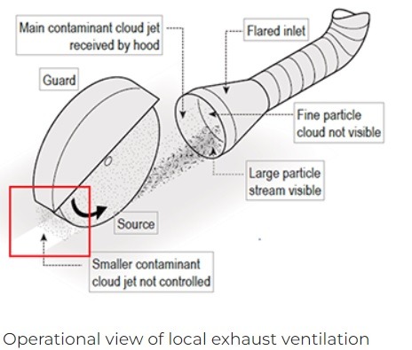
Any workers entering an engineered stone or silica cutting room must wear:
- a tight-fitting respirator (i.e. half face reusable, half face disposable, full face reusable or tight-fitting powered air purifying respirator (PAPR)), with written evidence of the worker passing a respirator fit test in the last 12 months which was performed by either the manufacturer or supplier of the respirator, an occupational hygienist, or a suitably trained consultant
- disposable overalls, which can be removed before leaving the workplace OR reusable overalls which can be removed at the workplace, bagged and laundered prior to re-wearing
The engineered stone or silica cutting room is cleaned regularly and progressively through the day – at a minimum frequency of once per day, and more frequently if required.
All off-cuts and dust generated are to be disposed of in sealed and labelled bags which are durable enough that they will not tear and release dust.
Any other controls outlined in that state or territory’s silica legislation or silica Codes of Practice are implemented at all times.
For the on-site mechanical processing of any silica containing products which are not engineered stone (e.g. for mechanical processing of natural stone, concrete, Portland cement, ceramic tiles, brick, fibre cement sheeting, etc.):
- Elimination of the risk has been considered and is not reasonably practicable
- A continuous feed of water over the cutting area (water delivery control) will be implemented when reasonably practicable
- Alternative wet dust suppression methods will be implemented when reasonably practicable (e.g. emulsions, sprays, curtains, mists, foams or other suitable liquids over the place where the dust is being produced)
- The work area will be isolated from all other people – for example by scheduling the works at an appropriate time, segregating the workplace into different work zones, or using a designated cutting room which contains:
- An intact ceiling or plastic shrouded area to encapsulate dust
- Sealed or covered mechanical air ducts
- Restricted access signage placed at the entrance
- An on-tool extraction system (Class H vacuum) will be attached to the tool / equipment when this is reasonably practicable
- Local exhaust ventilation systems (high efficiency air filtration systems) will be installed and used when this is reasonably practicable
- Respiratory Protective Equipment (RPE) will be worn as required
Monitoring of controls will be undertaken through Task Inspections, site walks and other inspections
When there is a need to perform mechanical processing of a silica contianing material, and the resulting airborne crystalline silica levels are uncertain (or if there is a higher potential risk of personal exposures exceeding the workplace exposure standards), air monitoring will be conducted by a Certified Occupational Hygienist.
Air monitoring is not a control measure but will be used in these higher risk circumstances to determine the effectiveness of the controls.
Workers who continually work with crystalline silica dust and are at risk of adverse health impacts through potential exposure (e.g. those who work in the engineered stone benchtop industry) are to undergo health monitoring through their employer, which is carried out or supervised by a specialist doctor.
Site Establishment and Presentation is a reflection of SHAPE and your own personal brand.
Prior to establishing site, key pre-construction activities have been completed which includes:
- Project Risk Register
- Project Delivery Plan
- Site Induction
- Hazardous Chemicals Register
- SWMS Review
- SSOW Review
- Electrical Survey
- Dilapidation report
- Evacuation Diagrams have been developed and posted using the Evacuation Diagram Tool
The project waste management strategy represents the most effective way to ensure site cleanliness and SHAPE housekeeping expectations.
Clean sites result in improved:
- Workplace productivity
- Worker behaviours
- Health and safety outcomes
- Quality outcomes = zero defects
Buildings constructed prior to Dec 31 2003 present a higher risk of asbestos containing materials being present – the building asbestos / hazardous materials register has been reviewed for the presence of ACMs and where required further inspections and sampling have been arranged via a hygienist.
Where the asbestos / hazardous materials register or hygienist report identifies asbestos or other hazardous materials, the hazards and controls are included in the Project Delivery Plan and Project Risk Register, and are communicated to workers and relevant visitors via the Site Induction.
Refer to the Asbestos Management Procedure and Part F of the Site Induction.
A project dilapidation report has been completed prior to commencing work on site.
Site lighting requirements are planned with respect to the new floor layout, safe access and egress. The quality of finishes may also be negatively impacted by inadequate lighting of work areas.
Site Signage
Signage is a reflection of SHAPE’s and your personal brand – it is always clean, free from damage, the current revision of the SHAPE standard signage template, and posted at approximately 1.5m to the centre line of the sign using appropriate mechanical fixings and/or concealed adhesive tapes, etc.
Note: only clear adhesive tape may be used when required – duct or packing tapes, etc. are not permitted.
Site entry signage is posted at all entries to site.
A site sign in / out station and register is in place at the point of entry.
To eliminate the need for workers to cross the site area without wearing PPE, worker PPE storage is available at the site entry, e.g. pigeon holes, shelving or coat hook arrangements.

A white board or electronic monitor is in place for general and daily pre-start communications.
Way finding and directional signage is posted in prominent locations to ensure clarity. Directions to Amenities, Office and Meeting Rooms are clear and up to date.

Internal site noticeboards are posted – generally in lunch rooms or where the site inductions take place.
Site specific signage is printed in colour, laminated and relevant to project specific details.

Task specific warning signage (e.g. “overhead works”) is posted in the vicinity of the hazard location.
Possibilities for external signage (e.g. hoardings and branding) have been investigated and confirmed if viable. Confirm Client and Building Manager requirements and consult with your General Manager or Commercial Manager.

A contact list with photos of the project team is located within site boundaries.
Access and Egress
Site access is suitably secured to prevent unauthorised access, theft or disturbance.
Designated material storage areas have been identified, and material is safely and neatly stored.
All walkways and access corridors are adequately lit and free of materials.
Protection of Existing Finishes
Protection is installed to all existing finishes to a high standard and maintained

Subcontractors are protecting their own work and they have an adequate supply of protection available on site, for installation to their completed finishes
- Signage is located on new and old finishes stating that care is to be taken
- Protection is monitored and rectified as required to maintain its effectiveness
A dilapidation report has been compiled on existing finishes and services, including photos and test results (for services).
Copies of the reports have been distributed to relevant stakeholders, e.g. building manager, client, consultant, etc.
Offices and Meeting Rooms
Existing or proposed office spaces / rooms are being utilised during the construction period where possible.

Site Office and Meeting Rooms have clear signage, and have either:
- Walls made from pre-finished, or painted board; and
- Polythene walls or barricades (on shorter term projects).
Walls / barricades are clean and in good condition.
Offices and Meeting Rooms have carpet and ceiling (where possible and appropriate).
All tables and chairs are clean and suitable for purpose.
The site office is not used as a storeroom.
A sample board or finishes schedule with labels and references is clearly displayed and signed off.

Architect’s graphics are on display (if available).
A variety of drink options are provided for meetings (e.g. coffee and tea making facilities are available, water, juice or soft drink are able to be offered during meetings).

Appliances are properly maintained, tested and tagged.
The Site Office includes the following items:
- A First Aid Kit with appropriate signage
- Site documentation & folders, which are organised and well-presented
- Site printer and copier (when required)
- Plan desk and plan hangers
- Waste bin (which is regularly emptied)
- Lockable storage
Working spaces for SHAPE Project team members, Corporate Services, visitors, consultants or other SHAPE employees has been considered and provided.
The current revision of the EHSQ Frequency Chart is displayed within the Site Office.
Where a full set up is not possible due to the size of the project, the Operations Manager or General Manager have been consulted.
A short range programme is clearly displayed and up to date.
The current construction programme is displayed on the wall.
Messing and Ablution Facilities
The Lunch Room / Change Rooms are separated from the work zone, cleaned regularly, have clear signage and have either:
- Walls made from pre-finished, or painted board
- Polythene walls or barricades (on shorter term projects)

Floor covering is able to be mopped.
The following appliances have been provided, and are properly maintained, tested and tagged:
- Water cooler
- Boiling water units or kettles
- Microwave oven
- Fridge
- Sink and mains water supply, if practicable
The lunch room table and chairs are clean and in good condition (amenities chairs must be industrial rated and not domestic plastic chairs).
The lunch area has adequate lighting and waste bins, and is kept clean from construction dust and fumes.
Toilet facilities are adequate for the number of workers and gender composition of the workforce and visitors.
If the exact make-up of the workforce and visitors are unknown, toilet facilities need to accommodate both males and females.
Sanitary disposal units are included in female closets.
Site Toilets contain adequate:
- Toilet paper
- Hand washing facilities
- Soap
- Rubbish bins
- Sanitary disposal
Toilets have a regular cleaning regime in place which is monitored.
Note: workers and visitors (client representatives) often associate the cleanliness of bathrooms and other site amenities with the management style of your project team – always ensure an appropriate cleaning regime is in place.
Where a full set up is not possible due to the size of the project, the Operations Manager or General Manager have been consulted to ensure that SHAPE’s workplace consultation requirements are met.
Subcontractor Activities
Cutting areas, specialist trade activity areas and storage areas are planned for and established on site to benefit site presentation, health, safety and quality outcomes.
Designated areas for the following have been identified, which are adequately signposted and protected:
- MDF Cutting Room
- Plaster mixing
- Pipe threading
- Paint storage and clean out
- Metal cut off / Drop saw
- Other wet trade mixing / wash down areas, as required
There is evidence that subcontractors are cleaning up after themselves daily.
Inspection and Monitoring
Works to Complete Lists are completed via Procore, which includes a subcontractor and consultant inspection regime being in place, to ensure timely observation and correction of quality-related matters, i.e. ideally after each client meeting or subcontractor meeting.
Procore QR codes are utilised and displayed to encourage ongoing defect management.
Best practices are being used on site and are being recognised.
New ideas are being implemented and being shared with the whole of SHAPE.
When construction work is carried out on a site that is near or adjacent to the property boundary or to any public place, the risks of site separation and public interface must be eliminated, isolated, or reduced.
During pre-construction, the project team reviews the scope of works with respect to the risk of unauthorised site access and public safety around the external perimeter of the site, for inclusion into the Project Risk Register and Project Delivery Plan.
There are Safe Systems of Work / SWMS in place and approved for all site separation activities, i.e. fencing, hoarding, etc. prior to the works commencing.
Permits and approvals (council and building management) are in place prior to erecting fencing, barricades or hoardings.
Overhead works in proximity of public areas are assessed and controls are implemented where required.
Site Fencing and Hoarding:
- Are of a suitable height and type to prevent climbing
- Prevent unauthorised access below the panels
- Are suitably wind and impact rated with installation and engineering certificates / records of inspection available on site
- Are comprised of non-flammable / fire retardant materials when hoarding / screening is located within 2m of any building face, or where hoarding or screening forms part of an emergency exit route for workers or building occupants / members of the public
- Where shade cloth or banners are attached to fencing or hoardings, appropriate wind loading controls have been implemented. Additional bracing and certification may be required
- Temporary fencing hand rails should be installed where there is a risk of pedestrians tripping over the fence feet, e.g. on or near a public walkway

- Vehicle entry gates are lockable and securely braced to prevent damage from wind loads and/or vehicle impact
- Pedestrian access is available – lockable and separate from vehicle access
- Site Entry/Construction Warning signage is posted at site entry points and at required intervals
- Temporary fencing must not be modified by anyone other than the contracted and competent installer
- Consideration has been given for access to fire services equipment (e.g. hydrants) in the placement of fencing or hoarding
- Egress or evacuation routes are not impeded by fencing or hoarding
- Public-facing hoarding and fencing are clean, well presented, freshly painted and combine the use of signage and graphics to reflect the SHAPE brand

Public Walkways:
- The risk of falling objects has been managed and controlled through the use of overhead gantries, crash decks, mesh screening, etc.
- External or public walkways are free of slip and trip hazards, have adequate lighting and have directional signage in place
- Pedestrian / traffic controllers are used to manage vehicle and equipment movements
- Where pedestrian ramps or ramping is required, consideration to Australian Standard 1428 (Design for Access and Mobility) must be considered, i.e. level of incline, distance travelled between landings, tactile indicators
External Impact to Site:
- Temporary switchboards situated in external work areas are locked at the end of each shift
- Water vessels are covered or emptied
- Materials and waste are secured / tied down for wind hazards
- Loading and unloading of plant and equipment is completed in accordance with the traffic management plan, road transport rules / legislation and permits
- Site excavations are suitably barricaded and sign posted
- Work activities which are external to the site envelope have adequate exclusion zones and warning signage
- Reinforcing bars / star pickets / impalement risks are suitably capped
- Building / construction elements are adequately braced to prevent collapse until structurally connected or braced
- Adequate night lighting is in place for emergency access
- Site security provisions have been considered and are in place, e.g. static guards, security cameras, monitoring systems, etc.
Internal Sites:
- Lift controls are programmed to prevent unauthorised access to SHAPE work areas or floors
- A physical barrier or catchment zone has been established where lift access cannot be secured
- On occupied floors the SHAPE site entry point signage restricts access
- The site is able to be secured at the end of each shift
- For high security sites, an electronic security system is in place, e.g. swipe card access, digital or push button security hardware, security turnstiles, etc.
- When internal stairwells/fire stairs are used for access between floors, controls are in place to prevent unauthorised access
- PPE Free Zones are clearly defined and provide safe access between the site entry and site office
This SMS provides practical guidance on the safe handling and storage of materials.
During pre-construction, the project team reviews the scope of works with respect to the safe handling and storage of materials, for inclusion into the Project Risk Register and Project Delivery Plan.
Consideration should be given to:
- Provision of storage facilities OFF SITE
- Scheduling of deliveries to prevent bulk loading
- Safe loading and unloading zones
- Traffic management
- Access to the building – e.g. use of existing lifts, stairs or provision of a materials hoist, etc.
- The types and sizes of material to be delivered or removed
- Public interface
- Manual handling controls
- Set down areas
- Designated subcontractor storage zones
- Isolation of materials – barricades and signage
- Security of materials
- Moveability of stored materials – e.g. materials are stored on pallets or mobile “A” frame racks
The Site Induction details project specific requirements for delivery, handling and storage of materials.
Consideration is given to loading and unloading activities that take place outside of the site envelope – as principal contractor SHAPE have obligations to ensure the safety of workers carrying out these activities, be it in the building loading dock or on a public road or place.
Management diagrams may be required to show designated loading/unloading zones and storage areas.
Subcontractor SWMS are reviewed using the SHAPE SWMS/SSOW Review to ensure delivery, handling and storage of materials hazards and controls are adequately addressed and specific to the project.
Key considerations:
- Unloading from vehicles
- Unloading in public locations – interface with vehicle and pedestrian traffic
- Manual handling techniques
- Use of mechanical aids
- Use of spotters
- Timing for deliveries
- Storage of materials
- PPE
- Workers are trained in manual handling.
Materials are not stored in access ways or areas of work.
If work is to be performed near to or in the vicinity of materials, a risk assessment has been undertaken to determine the hazards – any risk level above LOW risk will require the materials to be relocated to another suitable location.
All materials are stored on pallets or mobile storage racks – NOT directly on the floor.
Where there is a risk of materials falling, those materials are restrained with suitable load rated strapping.
Materials are NEVER leant against walls or partitions.
Glazing panel edges (new and demolition) are protected to prevent connection with body parts while being stored and transported.
Waste bins are not overloaded, i.e. no materials are protruding from the top of the bins.
Waste materials are not stored on the floor. If this cannot be achieved, isolation with barricading and warning signage is in place.
Designated areas for site boxes, platform ladders, EWPs, etc. are provided – subcontractors and workers are requested to only bring equipment on site when it is needed and removed as soon as possible on completion of the task.
New or existing finishes and fixtures to be reused are to be palletised.
For example:
- Ceiling tiles
- Carpet tiles
- Light fittings
- Workstation components

While demolition activities may be classified as either structural or non-structural, the nature of the hazards and controls are often applicable to both. Structural demolition and alteration will require a separate demolition work plan, permits and approvals.
During pre-construction, the project team reviews the scope of works with respect to structural demolition and alteration activities, for inclusion into the Project Risk Register and Project Delivery Plan.
Examples of structural demolitions and alterations may include:
- Creation of stair penetrations
- Demolition of lift shafts
- Demolition of concrete in-situ stairwells
- Demolition of load bearing
- walls and columns (which could be timber, masonry, concrete or steel)
- Demolition of floor or roof framing
- Demolition of a structure or part thereof
- Footing alterations
- Removal of suspended slabs
- Demolition of mezzanine levels
- Creation of openings (e.g. for windows and doors) within load bearing walls
- Alterations to plant and equipment structures (e.g. plant decks, HVAC units, chiller units)
The following legal requirements have been reviewed and considered:
- any statutory, regulatory, or other legal impediments that may prevent the demolition of the building
- permit applications, approvals, certificates, notifications, etc. have been submitted to relevant authorities
- the owner/principal is legally empowered to have the building structure demolished
- the owner/principal has identified all hazardous materials located on site, including asbestos, PCBs, lead paint, underground storage tanks, chemicals, etc., and has provided this information by way of a hazardous material register
- the owner/principal has obtained permission to occupy adjoining neighbours’ properties, including airspace, for the purpose of erecting protective scaffold/screens for the demolition works
- the owner/principal has provided all existing architectural, services and engineering drawings available for the demolition project
- tender/contract documents are sufficient and complete
Note in NSW only: demolition licence holders must ensure demolition workers who are required to undertake licensed demolition work have completed the course approved by SafeWork NSW:
- CPCCDE3016 – Identify Hazards on Demolition Sites and Apply Risk Management Strategies, OR
- CPCCDE3016A – Identify Hazards on Demolition Sites and Apply Risk Management Strategies
A review of the drawings has been conducted to identify:
- the principle structural materials (e.g. timber, masonry, steel, concrete) in the roof, floor, columns, and internal and external walls
- any secondary materials (non-structural) in ceilings, wall-panelling, partitions and floor finishes
- the location of service supply mains (water, electricity, gas) and the extent of reticulations
- the location of emergency services (fire detection and fire fighting)
- other services (sewerage, drainage, air conditioning, lifts)
A structural engineer has been engaged to provide advice on bracing, propping, needle works and overall works methodology.
The existing structural system has been checked for deterioration.
The elements resisting vertical load (e.g. floors, beams, columns, walls) have been identified.
The elements resisting horizontal load (e.g. service cores, shear walls, braced frames, rigid frames) have been identified.
Dial before you dig has been consulted and service provider drawings obtained.
A service search company has been engaged to verify and locate services.
Underground services have been identified and located, and their points of entry to and exit from the site.
Levels of basements, cellars, carparks and other underground areas have been determined relative to adjacent ground levels and adjoining basement or footing levels.
Retaining structures have been identified that provide support to adjoining properties.
The location, nature and condition of all Hazardous Chemicals identified in the Hazardous Chemicals Audit been identified on site.
The most suitable points of ingress to and egress from the site been identified for site personnel, demolition equipment and the removal of demolished materials.
A dilapidation report has been compiled, recording the condition of buildings on the adjoining sites, particularly where these abut a common boundary.
The need for, and the extent of, any required security fencing, hoardings, or overhead protection for footpaths has been determined and implemented appropriately.
A demolition work plan has been developed based on the documentation and on site investigations.
The work plan has a level-by-level procedure for stripping, breaking-up and removal of stripped and demolished materials.
From the level-by-level procedure, the nature, number and sizes of mechanical equipment, and number and skills of personnel to be deployed on the working level, has been determined.
The use of plant and equipment has been identified, managed and controlled within the project risk register, demolition plan and contractor safe systems of work.
Written advice from a structural engineer has been received, verifying the ability of the structure and propping to safely sustain the proposed loads
The work plan details restrictions on working hours, use of public thoroughfares, noise levels, etc.
The work plan includes a time-line showing the commencement of work, milestones and the completion of work.
Approval has been given to use the demolition work plan by the client/owner and other stakeholders.
Permanent and emergency entrances and exits have been established.
An appropriate site office and site amenities have been established. Consideration has been given to portable buildings or portable amenities away from the location of risk (relevant to the scope of works).
All site personnel have been inducted and trained in the work plan, safety procedures, and established procedures for dealing with emergencies (e.g. accidents, fires).
Check State Regulator requirements to ensure that the demolition contractor’s licence is verified as appropriate for the class of demolition activity.
All necessary plant, equipment and tools are available and in good working order.
A copy of AS/NZ 2601 demolition of structures is available.
A checklist has been developed for daily inspections, including but not limited to:
Before commencing work, the following are checked daily:
- All openings and elevated free edges are properly guarded
- Temporary bracing, shoring, or propping is tight, stable and secure
- Fire and safety services are operational and all other services to the working level have been properly disconnected
- Hazardous Chemicals have been removed from the working level
- Lines of communication to the supervisor are clear and operational
- All emergency access routes are clear of debris and clearly marked
Before leaving the work site, the following are checked:
- All partly demolished elements are stabilized
- All demolished materials have been removed or secured against inclement weather
- All fires or embers have been properly extinguished
- All emergency access routes are clear of debris and clearly marked
- All boundaries have been secured against unlawful entry
- All public thoroughfares are clear of demolished materials and any hazard is properly lit, guarded and clearly marked
Any alterations to bracing, propping, structural members or demolition method have been reviewed and approved by the structural engineer in writing, prior to the alterations taking place.
A documented structural engineer inspection is performed on the bracing, propping and structural members:
- at a minimum, once every 30 days
- after any significant weather event, repair, modification, alteration or incident which may affect the integrity of the bracing, propping or structural members
Traffic Management Controls are required to separate workers, members of the public and other pedestrians from vehicles such as cars, trucks, vans, buses, cyclists and powered mobile plant (e.g. forklifts).
During pre-construction, the project team reviews the scope of works with respect to traffic management activities for inclusion into the Project Risk Register and Project Delivery Plan.
Activities that involve or affect work in public areas or on public roads must be approved by local authorities.
Localised Traffic Management Diagrams for internal access requirements, building access, etc. may require building management approval.
The Traffic Management Diagram includes a site map, pedestrian and vehicle movements, the expected durations of interaction between vehicles and pedestrians, deliveries and loading activities, and the roles and responsibilities of people in relation to traffic management.
Standing site Traffic Management Controls are communicated via the Site Induction. Delivery drivers or suppliers, if involved in loading or unloading activities, are also inducted to site and perform their work in accordance with their approved SWMS.
Additional task-specific consultation takes place with workers, vehicle, plant and equipment operators, delivery drivers and suppliers to communicate hazards and controls in relation to traffic management risks. Evidence of this communication is documenting using the Record of Toolbox Talk or Pre-Start Meeting.
The hierarchy of controls should be applied (in order of preference) to:
- Eliminate the risk of being hit by mobile plant or vehicle
- If elimination is not possible, the physical separation of pedestrians from plant and vehicles is implemented to a standard appropriate for the level of risk (e.g. jersey kerbs, water barriers, temporary fencing, parawebbing and star pickets)
- Scheduling of work to avoid or minimise the interaction of pedestrians, vehicles or plant in the same area at the same time
- Engineering controls such as audible warning signals, flashing lights, automated boom gates, traffic light system
- Signage and road markings to manage vehicle and pedestrian traffic according to the Traffic Management Plan
Traffic Management Controls should consider and include:
- Traffic controllers and/or police controlling traffic
- Road closures, footpath closure and detours
- Appropriate lane configurations and approach speeds for the type of work being performed
- Dedicated mobile plant haul routes
- Temporary lighting for night works
- Exclusion zones around mobile plant performing slewing or overhead load movements (e.g. mobile cranes)
- Temporary signs and signalling devices are in place and operational
- Safe Work Method Statements (SWMS)
- Access for oversized vehicles, emergency vehicles, bicycles, local residents, people with disabilities, elderly and school children
Workers involved in the use of mobile plant, equipment, vehicles and traffic control are wearing task-appropriate PPE, e.g. high visibility clothing, ultraviolet (UV) protection, dust masks if there is the generation of dust, hearing protection, etc.
Competencies for mobile plant and vehicle operators have been verified and documented.
Note: Copies of Licences and/or Certificates are to be located within the site file, with expiry dates noted, if applicable.
For high risk activities such as the use of mobile plant and equipment, an Emergency Response Plan has been developed and trialled. The trial and associated corrective actions are documented in Record of Toolbox Talk – High Risk Activity Emergency Response.
The methods of communication defined within the Traffic Management Diagram and SWMS are available and in place, e.g. intercom/loud speaker, two way radios, traffic signal lights (portable or permanent), hand signals and other equipment.
Angle Grinders present considerable risk when used incorrectly or by people lacking experience with the equipment. Prior to using an angle grinder, consider if it is the right tool for the job – if not, do not use it
Prior to accepting the use of angle grinders, alternative tools, equipment and work methods have been considered, including but not limited to:
- Offsite cutting from the supplier
- Cold cut saws
- Sabre saws
- Mechanical sheers
- Rebar cutters
- Hand tools
- Oxy-fuel cutting
- Plasma cutting
Before using an angle grinder:
- The operator must be aware of the manufacturer’s instructions – these are generally available through an internet search of the equipment manufacturer’s company website
- Only use the correct cutting or grinding discs for the equipment – if you are unsure, consult the manufacturer’s instructions
- The cutting blade must inspected for damage or wear and be suitable for the material and task
- Only use blades and discs intended for the equipment – i.e. do not use blades designed for carving or wood shaping
- The use of saw blades / toothed blades in angle grinders can increase the risk of serious injury through biting and kickback, so if you are considering using saw blades or toothed blades in an angle grinder, reconsider if the angle grinder is actually the right tool for the job
- Your company’s safe systems of work must document appropriate hazards and controls specifically justifying the proposed use of angle grinders, before you start the task
- Ensure the grinder is the right size for the task. NB 9 inch or 230mm angle grinders are not permitted on SHAPE sites without a written risk assessment that has been approved by an Operations or EHSQ Manager
- Guards must be fitted
- All handles must be fitted
- Both hands are used to hold the grinder
- Work to be secured at all times
- Goggles / gasketed safety glasses must be worn
- Cut resistant full finger gloves must be worn
- Hearing protection must be worn
- A Hot Work Permit must be in place for the activity
- Fire warning / detection systems must be managed to prevent activation
- Building management must be advised that hot works are taking place
- Ensure you are aware of building management guidelines in relation to hot works and fire system isolations
- Adequate / suitable firefighting equipment is in the vicinity of the works and is within test date
- Assess the location of fire sprinklers and implement controls to prevent sprinkler activation
- Ensure there are no combustible materials, products, services or equipment in the vicinity of works
- Ensure cylinders, drums, tanks, gas or fuel lines have been decommissioned and purged prior to cutting or working nearby
- Ensure the maximum speed marked on the attachment is greater than the maximum speed marked on the angle grinder
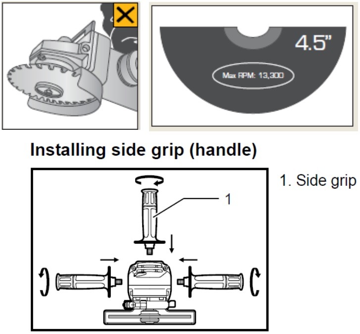
During pre-construction, the project team reviews the scope of works with respect to equipment, including the use of angle grinders, for inclusion into the Project Risk Register and Project Delivery Plan.
Designated cutting area(s) with a work bench, power supply, waste bin and firefighting equipment should be part of the project’s site establishment strategy for the use of angle grinders.
Tasks / trades that benefit from this sort of arrangement are:
- Metal stud and framing cutting activities – stud, track, furring channel, ceiling hangers
- Ceramic tiling – tile cuts
- Cable tray installation – hanging rods, uni-strut and cable tray
- Mechanical service installation – hanger rods and uni-strut
- Onsite aluminium joinery fabrication
Subcontractor SWMSs are reviewed using the SWMS Review to ensure job steps, hazards and controls relating to the use of angle grinders are detailed – including the use of task specific PPE.
Standing site rules regarding the use of angle grinders and task specific PPE are communicated via the Site Induction.
This includes the use of angle grinders fitted with automatic cut-off switches, commonly referred to as “dead man switches” or “paddle switches”.
Prior to the use of an angle grinder, a Hot Work Permit is required for each separate activity and consideration must also be given to the isolation of fire and smoke detection services and building management impairment notices.
Workers must be competent in the use of angle grinders – be aware that young or inexperienced workers present a greater risk of injury and must be instructed on the safe use of equipment by a competent person such as a qualified tradesperson.
If hot works are completed from height access equipment, ensure the equipment is protected from falling / flying hot debris, slag and embers.
NB suitable firefighting equipment must be positioned at the cutting area, i.e. within an EWP basket or scaffold deck
A 30 minute fire watch must be enacted during all work breaks and on completion of the hot works or shift.
Types of PPE for use of angle grinders:
- Dust mask – selection based on the product SDS for the material being cut, sanded or ground
- Eye protection – sealed googles, gasket rimmed glasses or face shield
- NB standard safety glasses are not adequate eye protection for the use of angle grinders
- Arms and legs – long trousers and long sleeved shirt – cotton or non-flammable material
- Feet – safety footwear – low cut safety footwear not permitted
- Hands – leather gloves or similar non-flammable / cut resistant material – must be full finger
A knife is defined as any hand held non powered cutting instrument or tool. Proper planning, training, management and monitoring of the safe use of knives is required to prevent cut injuries so far as reasonably practicable.
At the pre-construction phase the project team reviews the scope of works with respect to use of knives for inclusion into the Project Risk Register and Project Delivery Plan.
Following the development of the project Risk Register, all relevant information in relation to the use of knives is detailed within the project’s Site Induction Handout.
All workers are communicated site specific requirements for use of knives through the Site Induction process.
Subcontractor SWMS and SSOW are reviewed via the applicable SWMS Review or SSOW Review to ensure job steps relating to the use of knives and relevant hazards and controls are detailed.
NB. The use of knives must be identified separately from generic references such as the use of tools and equipment. Generic references will not be accepted.
Knives may not be used where there is a suitable alternative proprietary tool available for the purpose.
The use of a knife as a convenient alternative to another suitable tool is never acceptable and deemed a non-conformance to this SMS.
E.g. the use of a knife to strip cable insulation is not permitted.
The use of fixed and manual retracting blade knives for prying / pairing / whittling / carving / trimming excess materials is not permitted as there are generally other proprietary tools available for this purpose.
When a knife is deemed an acceptable option the following must be considered in order of preference:
- Use of a pressure sensitive auto retracting blade knife
- Use of a manual retracting knife
- Use of fixed blade knife
Where a manually retracting or fixed blade knife is deemed acceptable the contractor’s SWMS must detail the following controls:
- Workers must be trained in the correct use of knives
- Suitable cut rated gloves must be detailed specific to the use of knives
- Knives must only be used for the approved work method
- Always cut away from your body
- Fixed blade knives must be holstered in an appropriate holster or have cutting edges capped when not in use
- Fixed blade knives are never to be stored loose in toolboxes or tool bags unless they are holstered
- Manual retracting blade knives must be retracted after every use
The use of domestic type knives for tasks such as lagging or insulation activities are not permitted.
Trade quality long-bladed knives may be permitted if:
- They are the most suitable tool for the task
- They are able to be holstered
- The contractor’s SWMS details appropriate controls for use
The use of retractable craft or hobby knives and/or snap off blade type knives are not permitted. It is noted that specialist activities such as glazing and wallpapering require specialist blades that may be of the snap off type. These are permitted when documented appropriately under the subcontractor’s SWMS.
All workers involved in the use of fixed or manual retractable blade knives must complete a Toolbox Talk for the safe use of knives (based on the Use of Knives SHAPE Minimum Standard) at the start of every project
The use of knives will be monitored through Site Walk Observations and the Task Inspection processes.
Workers not complying with the requirements of this Use of Knives SHAPE Minimum Standard or their own SWMS will be managed in accordance with the SHAPE noncompliance procedure:
- Verbal warning
- Notice of non-compliance
- Exclusion from site
Example: a plasterer has a perceived need to use a fixed blade knife.
The contractor’s SWMS must include the use of the knife as a job step and assign hazards and appropriate controls.
Hazards include – cuts, abrasions, eye injuries, etc.
Controls include – use of full finger gloves, workers are trained in the use of knives, always cut away from body, wear safety glasses, knives are holstered when not in use, knives not to be used for pairing, wittling, trimming, prying, carving, etc.
Training – all workers permitted to use fixed blade knives must take part in safe use of knives training via a Toolbox Talk.
Trolleys are used to reduce the human manual handling requirements of transporting materials, tools or equipment. It is important to note however that trolleys carry their own risks, including the risk of trolleys tipping over which can serious injuries, and therefore trolleys should only be used after careful consideration of the hazards, selection of the appropriate type of trolley and a consistent implementation of controls for the safe use of trolleys.
During the pre-construction phase, the project team reviews the scope of works with respect to use of trolleys for inclusion into the Project Risk Register
Following the development of the Project Risk Register, all relevant information in relation to the use of trolleys is detailed within the project’s Site Induction Handout.
All workers are communicated site specific requirements for the use of trolleys through the Site Induction process.
The contractor’s Safe System of Work (SSOW) or SWMS identifies appropriate hazards and controls for the use of trolleys
Workers have been provided training and instruction by their employer in the correct selection and safe use of trolleys including correct manual handling techniques in accordance with the employer’s SSOW or SWMS
The type of trolley selected is suitable for the task being performed (e.g. trolleys designed to transport and store plasterboard are not suitable for transporting glass)
The size of trolley is suitable for the size of the sheet / panel / glass / materials or tools and equipment to be transported or stored
Materials and equipment are placed efficiently and methodically on the trolley to ensure the weight is evenly distributed and so that the operator(s) can see over the load
Large loads are broken down to smaller loads to reduce the amount of human force required to control and move the load. When panel, sheet or glazing trolleys are used to transport materials, the contractor’s documented SSOW or SWMS identifies an appropriate number of sheets per trolley to minimise the risk of trolley tip-overs due to uneven surfaces or the need to turn sharp corners. For example, for trolleys with a static load capacity of 1,000kg consider that the dynamic load capacity will be significantly reduced and may require contractors to:
- Limit standard plasterboard sheets (2400 x 1200 x 10mm) to approximately 6-8 sheets per trolley which amounts to approximately 150kg
- Limit non compressed fibre cement sheets (2400 x 1200 x 6mm) to approximately 5-6 sheets per trolley which will also weigh approximately 150kg
The condition of the trolley is always inspected prior to each use:
- The Safe Working Load (SWL) is displayed and legible
- Wheels / tyres are in good condition and are inflated to the correct pressure
- Breaks or wheel locks are present and in good working order
- Welds and bolted connections are in good condition – there are no signs of cracking
- Hydraulic systems are in good working order
- The trolley operates, moves and steers freely as intended when not under load
Load-rated tie down straps are used and are in good working condition
When required, the trolley’s restraint bar is present and in good working condition (e.g. for glazing or stone trolleys)
For glazing trolleys, protective bearing material is in place and in good condition (i.e. rubber, neoprene, timber or felt/carpet, etc.) to ensure glass does not contact the metal surfaces / edges of the trolley
Sharp edges of loads are protected at all times
The path of travel has been assessed and is clear of obstacles and other slip, trip and fall hazards. If blind corners exist, you may require support from others to guide the load and ensure the safety of others
The work area is suitable for the wheel size (e.g. there are no floor level / surface changes greater than 5-10mm)
Workers always push when moving loads (you can’t see where you’re going when pulling backwards)
A safe speed is always maintained while moving trolleys to keep the trolley under control
Trolleys are not left unattended in access ways or work areas – trolleys are always stored in the designated materials and equipment storage areas
This SMS provides practical guidance on SHAPE minimum standards for Verification of Competency (VoC).
During the pre-construction phase, project specific activities involving the use of mobile plant & equipment are identified within the Project Risk Register, with training and competency requirements further detailed within the project Project Delivery Plan.
Note: Training and competency requirements may relate to subcontractors or SHAPE project team members.
A review of relevant contractor SWMS and SSOW using the applicable SWMS Review or SSOW Review will further determine the types of plant & equipment to be used for specific tasks, and any qualifications or licenses required to operate the plant & equipment.
Prior to the use of mobile plant or equipment, documented evidence of competency for the operation of the mobile plant and equipment has been copied and maintained on site, and is kept with the worker’s Site Induction Record.
Refer to the Plant and Equipment SHAPE Minimum Standard and Plant and Equipment Procedures for further requirements relating to management controls for plant and equipment.
The following can be used as evidence of competency:
- A High-Risk Work Licence issued by a State or Territory under the National Certification System as per the legislation; or
- Where a High-Risk Work Licence is not required by legislation:
A Licence or Certificate of Competency issued under previous State or Territory legislation for which there is no longer a High Risk Work Licence required, e.g. load shifting equipment; or
- A Statement of Attainment or Certificate issued by a Registered Training Organisation (RTO) for the successful completion of the appropriate unit of competency in the Nationally Recognised Training (NRT) package; or
- Evidence of a formal VoC assessment against defined competency standards, which should:
- be completed, or confirmed as having been completed, by the accredited company to an acceptable level, such as the relevant NRT, internal VoC process, or equivalent;
- include a detailed and documented assessment standard;
- be completed by a person (or persons) who meets the documented competency as defined by the company to conduct a VoC assessment; and
- be evidenced by a signed, completed VoC assessment.
A letter signed by an employer or supervisor claiming that the worker is competent is not an acceptable form of verification of competency.
Plant and Equipment activities that require verification of competency:
- Scaffolding – Basic, Intermediate, Advanced
- Dogmen and Riggers – Basic, Intermediate, Advanced
- Crane Operation
- Mobile concrete placing boom operation
- Forklift operation
- Tele-handler operation
- Hoist operation
- Elevating work platform operation
- Earthmoving equipment operation
Note: there are several other trade related or hazardous activities that require verification of competency, including but not limited to:
- Confined Space entry – see Confined Spaces SHAPE Minimum Standard
- Asbestos Removal – see Asbestos Management SHAPE Minimum Standard
- Electrical Work – see the Electrical Management SHAPE Minimum Standards
- Formwork and Falsework – see the Formwork and Falsework SHAPE Minimum Standard
- Restricted Electrical work
- Plumbing and Drainage
- Work at Heights – see Working at Heights SHAPE Minimum Standards
- Structural Demolition and Alteration – see Structural Demolition and Alteration SHAPE Minimum Standard
For further information on competency requirements refer to the SHAPE Licenses for High Risk Work and Plant and Equipment Guide.
Examples of high risk work licences
Working at heights is a high risk activity and a leading cause of death and serious injury in Australia, SHAPE has specific obligations to manage the risk, as far as is reasonably practicable, of someone falling from one level to another.
During pre-construction the project team reviews the scope of works with respect to work at height activities for inclusion to the Project Risk Register and Project Delivery Plan.
Controls are developed and implemented with consideration to the specific Working at Height Hierarchy of Controls which are outlined in the National Code of Practice for the Prevention of Falls in General Construction, and shown in the attached image
Emergency procedures / rescue plans are documented for the retrieval of a fallen or injured person inside the Project Risk Register or a separate documented emergency plan.
All workers are communicated site specific requirements for work at heights hazards through the Site Induction.
All “at-risk” roof access or roof works are controlled by the use of the Roof Access Permit.
At-risk roof access is when there is a physical work activity being performed on the roof, and the risk of a person falling or falling objects is associated with the access to the roof.
Industrial rope access / abseiling work is controlled by the use of the Rope Access Permit.
Personnel involved in work at heights have provided evidence (and a copy is kept on file) that they have completed a nationally recognised training course in working at heights, i.e. one of:
- RIIOHS204A
- RIIWHS204D
- RIIWHS204E
- CPCCCM1006A
- CPCCCM2010A
- CPCCCM2010B
- CPCCCM2012
Existing height access equipment, including stairs, ladders and access hatches have been risk assessed to ensure their suitability for use and to address any training requirements for their safe use.
Safe access and egress has been considered, planned for and provided for personnel needing to access areas such as:

- Mechanical plant platforms


- Removal of façade glass for air intake louvers


- Formwork
- Scaffolds
- Stair penetrations

When access or egress arrangements change, these are clearly communicated to the workforce and emergency response plans are updated to reflect the changes
Edge protection / guardrail systems are not put into active service (i.e. workers are not permitted in the area) until a handover certificate has been provided to SHAPE (completed by an Advanced Scaffolder, engineer or the guardrail system designer or installer) after an initial inspection that verifies the edge protection / guardrail system has been installed in accordance with AS 4994 – Temporary Edge Protection, the manufacturer’s instructions, any other relevant legislation, codes of practice or Australian standards, or an engineered guardrail plan (if a non-proprietary system is to be used).
Documented inspections on the edge protection / guardrail system and the supporting structure are performed to ensure the guardrail system and structure are erected in accordance with the manufacturer’s instructions, AS 4994, or the guardrail drawing / plan (if applicable):
- Before it is used by workers; AND
- At a minimum, once every 30 days (in accordance with AS/NZS 4576 – Guidelines for Scaffolding). Note: the requirement for minimum 30 day inspections applies to both scaffold and non-scaffold type edge protection / guardrail systems on SHAPE sites; AND
- After any significant weather event, repair, modification, alteration or incident which may affect the integrity of the structure
Records of these inspection and maintenance activities are kept on site.
Harnesses have current inspection records – copies maintained in site file.
Anchor points have been installed /assessed by a qualified person and are rated for the required work, i.e single person or 2 person anchor (refer to the Anchor Points SHAPE Minimum Standard for further information on suitable qualifications for anchor point installers / assessors).
Current inspection records for anchor points and other height access safety systems have been reviewed and copies maintained in the site file.
Exclusion zones and signage have been erected below drop zones.
During preconstruction, consideration is given to perimeter fencing and internal barricading, with controls documented in the Project Risk Register.
The locations of scaffolding and the highest point of any structure from which an object could fall are considered, and the Calculator for Hoardings and Fencing at a Construction Workplace (available on ToolBOX) is used to determine the appropriate temporary fencing, hoarding or gantry controls required to mitigate the risk of falling objects.
Depending on the angle between the fence or barricade and the highest point of the scaffold or structure, different types of hoarding or barricades are required:
- Less than 15º: A barricade or hoarding at least 900mm high.
- Between 15º and 30º: A hoarding at least 1,800mm high.
- Between 30º and 75 º: A fully sheeted hoarding at least 1,800mm high.
- Greater than 75º: A gantry is erected.
Hoarding or barricading must be installed on each side of the scaffold or structure from which an object could fall. The hoarding must withstand specific forces:
- 500N per m² applied over 1m² at the top of the hoarding (midway between any post and its nearest post) without permanent deformation.
- 950N applied over 1,500mm² at any point on the hoarding without fully penetrating the hoarding.
Hoarding or barricading may have gaps to minimise wind resistance, if the gaps are no larger than are reasonably necessary.
Hoarding or barricading, if it is part of a gantry, must extend to the gantry’s overhead platform.
The erection and installation of fencing, hoarding, barricading, and gantries must be completed before work commences.
Areas interacting with public spaces, such as roads and footpaths, must have appropriate measures to prevent accidents.
If gantries cannot be installed, the area must be closed or catch nets installed.
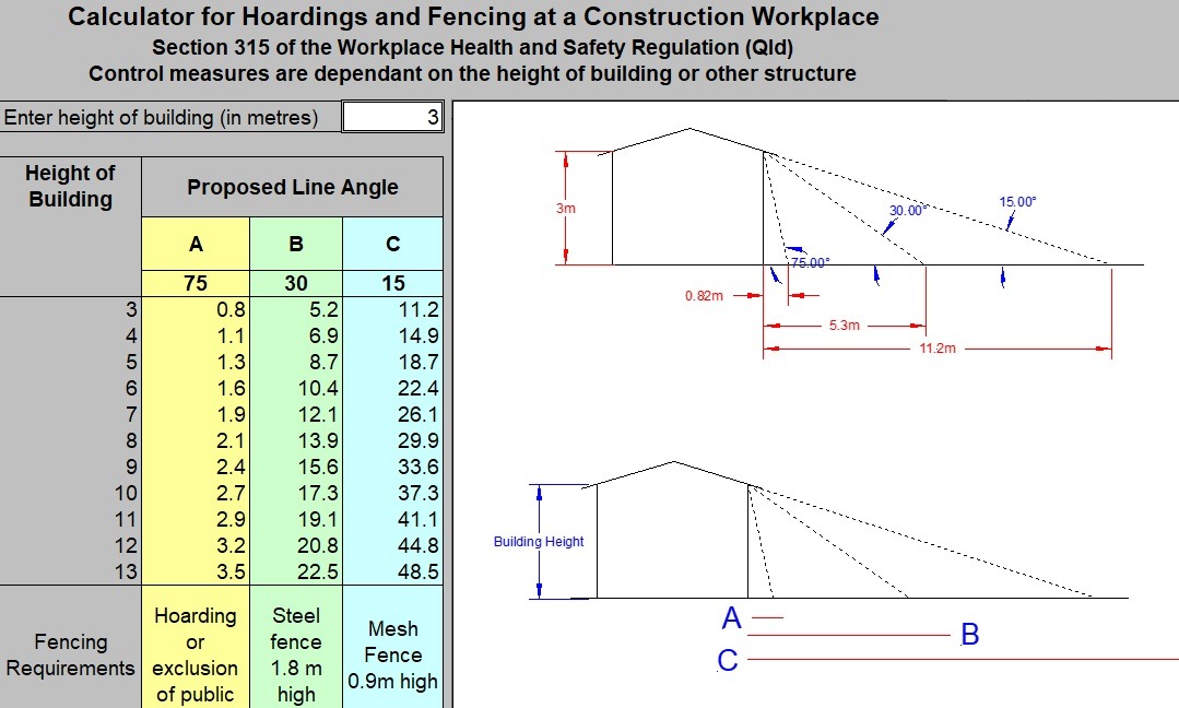
Warning signage is appropriate to the hazard and posted at regular intervals.
Temporary structures such as scaffold landing decks or gantries must display a sign indicating the load rating and loading plans based on engineered design requirements – this information must also form part of the Site Induction content or a separate Toolbox Talk.
Where a ladder other than a platform ladder is being used, a documented risk assessment is in place. Workers have been Toolbox Talked regarding the specific requirements and controls for ladder use.
Perimeter glazing has been risk assessed with regards to damage and risk of falls and falling objects.
All penetrations are identified and physical barriers installed.
Exclusion zones are defined when working in close proximity to windows, penetrations, excavations, stairwells, stored materials and equipment, prior to using height access equipment:
- Work platforms.
- Trestles,
- Platform ladders,
- EWPs, and
- Mobile Scaffolds
Working at heights is a high risk activity and a leading cause of death and serious injury in Australia. SHAPE has specific obligations to manage the risk, as far as is reasonably practicable, of someone falling from one level to another.
During pre-construction the project team reviews the scope of works with respect to work at height activities for inclusion to the Project Risk Register and Project Delivery Plan.
Emergency response procedures in relation to the use of height safety equipment are documented in the Project Risk Register or a separate documented emergency plan.
Where existing height safety systems exist, building management requirements for roof access are considered and included in Project Risk Register.
All workers are communicated site specific requirements for work at heights hazards through the Site Induction.
Subcontractor SWMS are reviewed via the SWMS Review and the Project Risk Register to ensure work at heights activities, hazards and controls (including emergency response plans) have been addressed when appropriate.
Note: Generic references to height access equipment not relevant to contractor activities must be removed / struck out of SWMS.
Roof Access Permits are in place for entry into roof spaces, or for any other at-risk roof access requirements.
At-risk roof access is when there is a physical work activity being performed on the roof, and there is a risk of a person falling or falling objects associated with the access to the roof.
Rope Access Permits are in place for industrial rope access / abseiling works
If existing height safety equipment is to be used (anchor points, static lines, access ladders, etc.) the project team has obtained the system’s design documentation from the building owner / manager.
If this does not exist then the system or equipment has been reviewed and approved in writing by a structural engineer or a height safety equipment installer.
If a new height safety system is to be installed, the selection of the system and associated equipment is performed by a height safety manager in accordance with AS 1891 – that is, a person who has completed additional height safety theory, and a person who has acquired the technical skills specific to the work and risk and systems management.
This means that height safety operators, supervisors or equipment inspectors should not design or select new height safety systems without the involvement of a height safety manager.
The design of the anchor system is reviewed in consideration of the work to be performed to ensure the equipment is being used in accordance with the design parameters.
For example:
- Number of persons per point
- Fall arrest or fall restraint
- Use of static lines and/or inertia reels compatibility
- “Sheer” and “Pull” load ratings
People required to wear a harness must provide documented evidence (and a copy is kept on file) they they have obtained a “Working at Heights” competency, i.e. they have completed a nationally recognised training course in one of:
- RIIOHS204A
- RIIWHS204D
- RIIWHS204E
- CPCCCM1006A
- CPCCCM2010A
- CPCCCM2010B
- CPCCCM2012
Static lines are only installed to certified anchor points by an IRATA or SPRAT Rope Access Level 3 technician, or a person with Advanced Rigger competency.
The use of building elements as tie points for static lines – such as structural steel framing or concrete structures – has been reviewed and approved in writing by a structural engineer, IRATA or SPRAT Rope Access Level 3 technician, or a person with Advanced Rigger competency.
Prior to use, anchor points will be inspected by a person trained in Working at Heights in accordance with the list of courses provided above (in Item 11).
Existing anchor points are within their test date prior to use – the required frequency is every 6 months.
Anchor points are only used within their design parameters for pull and shear loads.
Newly installed anchor points are installed by a qualified and experienced height safety installer who has been trained in the manufacturer’s installation requirements.
Newly installed anchor points are accompanied by a pull test certificate which has been given to SHAPE.
Anchor points are only used within their design parameters for pull and shear loads.
Each piece of height access equipment used (e.g. belts, harnesses, lanyard assemblies, connectors, fall arrest devices including common devices) are visually inspected by the competent Operator before and after each use.
Equipment that requires ongoing maintenance will be maintained in accordance with manufacturer’s instructions and AS 1891 – Industrial Fall-Arrest Systems and Devices.
Each piece of height access equipment used (e.g. belts, harnesses, lanyard assemblies, and associated personal equipment, including fall arrest devices, ropes and slings) is inspected by a height safety equipment inspector as a minimum every 6 months, as well as after being involved in any fall arrest, if the equipment has been deemed potentially unserviceable, or more frequently if recommended by the manufacturer or supplier.
Note: the site manager must copy or photograph these records prior to work commencing.
Emergency Response procedures are documented and tested for the use of height safety equipment in both “Fall Restraint” and “Fall Arrest” scenarios.
Note: the Record of Toolbox Talk – High Risk Activity Emergency Response is to be used as evidence of testing.
A Plant and Equipment Induction has been completed for all plant and equipment that is used as part of the activity (including for emergency response). Each item of plant and equipment is documented in the Plant and Equipment Register.
Exclusions zones and warning signage are considered and erected where there is a risk of falling objects present.
The use of proprietary tool and equipment tethers is considered where there is a risk of falling objects. DIY or makeshift tethers are not permitted.
Working at heights is a high risk activity and a leading cause of death and serious injury in Australia. SHAPE has specific obligations to manage the risk, as far as is reasonably practicable, of someone falling from one level to another.
During pre-construction, the project team reviews the scope of works with respect to work at heights activities for inclusion into the Project Risk Register and Project Delivery Plan. Where applicable, emergency response for work at heights and building management requirements for roof access with ladders must be considered and included in controls.
Following the development of the Project Delivery Plan and Project Risk Register, all relevant information in relation to work at heights using ladders is detailed within the Site Induction Handout.
All workers are communicated the site specific requirements for work at heights and the hazards of ladders, which is recorded through their completion of a Site Induction Record.
Subcontractor SWMS are reviewed using the SWMS Review to ensure work at heights activities, hazards and controls including emergency response plans have been addressed when appropriate.
Note: Generic references to height access equipment not relevant to contractor activities must be removed / struck out of SWMS.
Roof Access Permits are completed for any activities involving access inside roof spaces or roof tops using ladders.
Platform ladders are not the preferred option for height access working, and should not be used if there is a more suitable and stable working platform suited to the task.
Platform ladders may be used if suitable for the type of activity being performed.
Both feet must remain on the platform of the ladder at all times it is in use (i.e. rungs are for ascending and descending only, not for working from).
Platform Ladders are industrially rated, have a minimum guardrail height of 900mm and a minimum platform size of 400mm x 400mm.
Ladders with guardrails lower than 900mm or a platform size of less than 400mm x 400mm (sometimes referred to as “Step Platform Ladders”) are not permitted to be used on SHAPE projects without a documented and approved risk assessment.
Trestles or ladders (other than a platform ladder) are not to be used for working from unless a documented risk assessment within the SWMS, SSOW or Pre-Start identifies why there are no other suitable alternatives and the risk assessment has been accepted and signed by the SHAPE Site Representative.
Ladders used by all workers, including electricians, are made of fibreglass where LIVE cables / services hazards exist.
Tools and equipment are not stored on platform ladder platforms.
Drop zones around platform ladders require exclusion zones around them to prevent workers being impacted by falling objects.
Use of builder’s / extension type ladders must be risk assessed, with hazards and controls detailed within the contractor’s SWMS.
Note: In any case builder’s / extension ladders may only be used for access and inspection activities – not work activities.
All ladders:
- are load rated minimum industrial rating (i.e. are not rated domestic grade)
- are not used if missing fixings or if bracing is damaged or missing
- are not used if foot pads are damaged or missing fixings
- are not used if legs are cracked, twisted or damaged
- are not moved (walking the ladder) whilst a worker is still on the ladder
- are used with 3 points of attachment when ascending and descending the ladder, i.e. 2 hands and 1 foot, 2 feet and 1 hand
Note: This requirement will in most cases prevent workers from physically carrying tools and equipment while using the ladder unless stored in a tool belt / bag.
Platform Ladders:
- work is always performed from the ladder platform – not the steps
- must be positioned to ensure the worker is facing the front guard rail at all times
- a rear guard rail must be in place and used for platform ladders with platforms over 1.8m

- are not to be used in proximity of stored materials or equipment, where a fall onto the stored equipment would increase the consequences of injury
- are not used within 2 metres of plate glass glazing / windows unless additional controls have been considered and implemented, e.g. glazing protection
- are not used in the proximity of a live edge or open penetration unless a separate risk assessment has deemed the level of risk is manageable through additional controls – safe working distance from live edge calculation (working height + height of worker + plus 2 metres)
Builder’s / extension type ladders:
- are positioned on a firm flat surface (consider using ladder safety devices like leg levellers, anti-slip gutter guards and stabilisers)
- are secured top and bottom should be angled at a ratio of 1:4. That is, position the base of the ladder 1 metre away from the structure for every 4 metres of height
- are only to be used when a risk assessment demonstrates that this is the most suitable piece of height access equipment
- materials and ladders are not to be transported or carried during the use of a builder’s ladder
Working at heights is a high risk activity and a leading cause of death and serious injury in Australia. SHAPE has specific obligations to manage the risk, as far as is reasonably practicable, of someone falling from one level to another.
During pre-construction, the project team reviews the scope of works with respect to work at heights activities on mobile scaffolds for inclusion into the Project Risk Register and Project Delivery Plan. Emergency response procedures for the use of mobile scaffolds is documented in the Project Risk Register or a separate documented emergency plan.
Following the development of the Project Delivery Plan and Project Risk Register, all relevant information in relation to work at heights using mobile scaffolds is detailed within the project Site Induction.
All workers are communicated the site specific requirements for work at heights, which is recorded through their completion of a Site Induction Record.
Subcontractor SWMS are reviewed using the SWMS Review and Project Risk Register to ensure work at heights activities, hazards and controls including emergency response plans for scaffolds have been addressed when appropriate.
Subcontractor SWMS specifically address methodologies for the safe erection, alteration and dismantling of scaffolds in accordance with AS 4576 – Guidelines for Scaffolding and the applicable scaffolding Codes of Practice.
Note: Generic references to height access equipment not relevant to contractor activities must be removed / struck out of SWMS.
Emergency Response procedures are documented where required, and are tested for the use of scaffolds.
Note: the Record of Toolbox Talk – High Risk Activity Emergency Response is to be used as evidence of testing.
All mobile scaffolds are considered as plant and equipment which require the Plant and Equipment Induction to be completed. Each item of equipment is included in the Plant and Equipment Register.
All mobile scaffolds (regardless of the potential fall-height from the top platform) must:
- Be installed in accordance with the manufacturer’s instructions
- Be used in accordance with the manufacturer’s instructions
- Be erected on a flat and level surface
- Have outrigger bracing installed in accordance with the manufacturer’s instructions
- Display the manufacturer’s instructions i.e. a stick on label or printed copy
- Have the load rating of the scaffold assessed for the scope of work, and allow a minimum buffer of 100kg to ensure the scaffold is never over loaded. i.e. 450kg load rating = load to a max of 350kg only
- Have exclusion zones established and warning signage displayed where there is a risk of falling objects

- Never be positioned so that the worker has to overreach or work through the scaffold hand rails
- Be included in the SWMS for the worker intending to use the scaffold. The worker has been trained in the safe use of the scaffold and has signed onto the SWMS
- Be inspected by the worker prior to every use, to ensure the scaffold has not been altered and is safe for use
- Have wheels locked prior to and while using the scaffold
- Be dismounted by workers prior to moving the scaffold
- Workers must:
– Carry tools and equipment in tool belts to allow hands to be free when ascending or descending from the scaffold
– Pass materials up or down from platform level as required – Ensure materials are not stockpiled on the platform
– Never stand on or climb the handrail, diagonal braces or frames
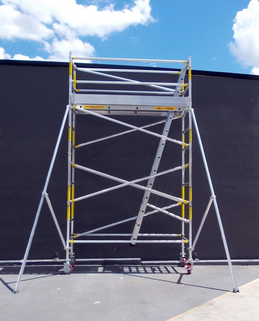
If the fall-height from the scaffold’s top working platform will be more than 4 metres, anyone erecting, altering or dismantling the scaffold at a workplace must hold an appropriate scaffolding certificate of competency, or be a trainee under the direct supervision of a certificate holder.
The minimum nationally uniform certificate class required is basic scaffolding (class code SB).
A licensed and qualified scaffolder directly supervising a trainee must be specifically authorised by the employer to oversight the trainee.
If the fall-height from the scaffold’s top working platform will be more than 4 metres, the scaffold must also:
- Display a current inspection tag (scafftag) at all times, with handover certificates available on file

- Be modified only by a ticketed scaffolder (minimum of basic scaffolding – class code SB)
- Be reinspected and retagged after every modification
- Be reinspected every 30 days by a ticketed scaffolder
If the fall-height from the top platform will not exceed 4 metres:
- A ticketed scaffolder is not required, however the erection, dismantling and any modifications are to be performed by a person who has been adequately trained and instructed in the erection and dismantling of that brand and model of scaffolding system (e.g. verification of competency by employer is acceptable. Refer to the Verification of Competency SMS)
- The scaffold is not required to display a scaffold tag
- The scaffold is still to be reinspected every 30 days or after every alteration by the person deemed competent to do so
Where scaffold is incomplete or has been observed as being a hazard, an incomplete scaffold sign must be attached and workers are prevented from accessing or using the scaffold.
The use of mobile scaffolds is monitored via the Procore Site Inspection Checklist (scaffolds <4m section) and Task Inspection.
Working at heights is a high risk activity and a leading cause of death and serious injury in Australia. SHAPE has specific obligations to manage the risk, as far as is reasonably practicable, of someone falling from one level to another.
During pre-construction, the project team reviews the scope of works with respect to work at heights activities on modular scaffolds for inclusion into the Project Risk Register and Project Delivery Plan. Emergency response and rescue has been considered when selecting the type of stair used to access and egress the scaffold.
Emergency response procedures for the use of modular scaffolds is documented in the Project Risk Register or a separate documented emergency plan.
Emergency Response procedures for the use of modular scaffolds are tested by relevant workers prior to work commencing.
Note: the Record of Toolbox Talk – High Risk Activity Emergency Response is to be used as evidence of testing.
Following the development of the Project Delivery Plan and Project Risk Register, all relevant information in relation to work at heights using modular scaffolds is detailed within the project Site Induction.
All workers are communicated the site specific requirements for work at heights and the use of modular scaffolds during their Site Induction, including relevant sections of the scaffold plan / design, details of weight distribution / load placement in accordance with engineered design requirements and exclusion zones where relevant. Delivery of this information is recorded through the completion of a Site Induction Record.
Signage is prepared for installation on site to ensure the weight distribution / load placement requirements are complied with at all times.
Subcontractor SWMS are reviewed using the SWMS Review and Project Risk Register to ensure work at heights activities, hazards and controls including emergency response plans for scaffolds have been addressed when appropriate.
Subcontractor SWMS specifically address methodologies for the safe erection, alteration and dismantling of scaffolds in accordance with AS 4576 – Guidelines for Scaffolding and the applicable scaffolding Codes of Practice.
Note: Generic references to height access equipment not relevant to contractor activities must be removed / struck out of SWMS.
Risk planning / assessment has been completed to ensure that the location of the scaffolding is not hazardous to workers, other mobile plant and vehicle traffic that may move around the site, and pedestrians passing the site.
The scaffolding design is registered with the relevant state or territory regulatory authority.
The design registration number is readily accessible in the vicinity of the scaffolding.
Consideration is given to ensuring the type of scaffolding selected is suitable for the work that needs to be performed.
When simple modular scaffolds under 4m (measured from the top working platform to the ground) are erected and used in full compliance with the manufacturer’s specifications, and the modular scaffold is not located near another hazard such as powered mobile plant or a live edge, a risk assessment may be documented (in the Project Risk Register) which determines that a scaffold plan / design is not required.
Edge protection / guardrail systems are not put into active service (i.e. workers are not permitted in the area) until a handover certificate has been provided to SHAPE (completed by an Advanced Scaffolder, engineer or the guardrail system designer or installer) after an initial inspection that verifies the edge protection / guardrail system has been installed in accordance with AS 4994 – Temporary Edge Protection, the manufacturer’s instructions, any other relevant legislation, codes of practice or Australian standards, or an engineered guardrail plan (if a non-proprietary system is to be used).
For any modular scaffolds that are installed outside the manufacturer’s standard parameters, or that are greater than 4m high (measured from the top working platform to the ground), or that are of a more complex nature (such as cantilevered, spurred, hung, birdcage, suspended or other swing stage scaffolds, or any scaffold structure trafficable by members of the public), an engineer provides written approval for the scaffold design / plan.
The scaffolding contractor has reviewed the scaffold plan / design, to identify or anticipate issues and fix them before they occur on the construction site. The scaffold design work includes SHAPE and other contractors with special requirements for when using the scaffolding. The scaffold plan / design is submitted to SHAPE prior to erection commencing.
A qualified engineer provides written approval for any non-standard scaffold designs or design features.
No changes or modifications are made to modular scaffolds unless the scaffold plan / design has been updated and approved in writing by the scaffold designer / engineer, and then the authorised changes may only be implemented by the project’s qualified and contracted scaffolders.
The Scaffold Alterations Warning Sign or Scaffold Alterations Warning Sticker is fixed to the modular scaffold in prominent locations on each level (spacings no greater than every 5 metres or every 3rd bay) to warn other trades that unauthorised alterations or modifications to modular scaffolds will result in their removal from site.
Suspended or swing-stage scaffold components are to be inspected for damage, wear and cracks before use and at pre-determined intervals. As some cracks may not be visible to the eye, non-destructive testing is to be performed to check for cracks in high-stress areas (e.g. dye penetrant testing) at least once every three years.
External perimeter scaffolds more than 8m high (measured from the top working platform to the ground) and a length of more than 60 lineal metres, are provided with at least two means of access and egress, one of which is suitable for emergency stretcher access.
Where the scaffold design permits, all modular scaffolds are fully encapsulated with suitable non-flammable / fire retardant containment screening / mesh to control the risk of falling objects.
When the scaffold design does not permit the use of non-flammable / fire retardant containment screening / mesh, the project team will seek this advice in writing from the scaffold designer and ensure a risk assessment is undertaken and subcontractor safe systems of work are developed to control the risk of falling objects.
This includes modular scaffolds constructed for access requirements only (e.g. scaffold access stairs).
The risk to the public been addressed and managed, e.g. falling objects, trip hazards, impact with components.
The risk of unauthorised entry to the scaffolding has been adequately controlled.
If exclusion zones have been selected as a control measure, they must prevent:
- Persons from being hit by falling objects
- The scaffold coming into the vicinity of overhead powerlines
- Other plant and vehicle traffic from entering the zone around the scaffolding
Scaffolding components are compatible with the scaffold system.
Building structures, materials, foundations and underground services have been assessed and controls are in place prior to starting erection of the modular scaffold. This is to ensure that scaffold foundations are able to carry and distribute all the weight of the scaffold, including any extra loads placed on the scaffold such as perimeter containment screens.
Concrete slabs or other building elements that modular scaffolds are being erected on have had their bearing capacity assessed by a structural engineer or the scaffold designer.
Soil or other natural substrates that modular scaffolds are being erected on have had their bearing capacity assessed by a geotechnical engineer and this information has been provided to the scaffold designer.
Scaffold platforms over four metres have been erected by an appropriate High Risk Work licence holder (i.e. Scaffolders, SB, SI, SA or Advanced Rigger RA)
Erector/s of the scaffolding have been provided with relevant training (SB – Basic Scaffolding, SI – Intermediate Scaffolding, or SA – Advanced Scaffolding), and this training is documented and verified.
Scaffolding has been erected with suitable ties at specified distances to make it stable from movement or collapse, as defined by a structural engineer or scaffold manufacturer.
Cast-in anchors or ‘through bolts’ (i.e. pass through a wall) are preferred to post-installed anchors for securing scaffold ties because of possible failure due to faulty tensioning or epoxies.
The step heights and goings in a scaffold stair system should be consistent within a straight run of steps between landings. Where there is a change in direction between landings, any difference in step height from the scaffold stair to an access or egress point should be minimised so that it is no more than 300 mm.
Added loads to the scaffold (e.g. fitted rubbish chutes, hoarding panels attached at the lower levels), have been incorporated into the scaffold plan / design drawings.
Scaffold being used as a fall arresting platform has:
- an unobstructed landing area of at least 675mm wide, able to withstand a fall impact
- if the slope of the surface or roof is under 26 degrees, the fall arresting platform is no more than 1m below the surface or roof
- if the slope of the surface or roof is over 26 degrees, the fall arresting platform is no more than 300mm below the surface or roof
A documented inspection on the scaffolding and the supporting structure is performed to ensure the scaffold and structure are erected in accordance with the manufacturer’s instructions, AS 4994 (or the scaffold drawing / plan if applicable):
- Before it is used by workers; AND
- At a minimum, once every 30 days (in accordance with AS/NZS 4576 – Guidelines for Scaffolding); AND
- After any significant weather event, repair, modification, alteration or incident which may affect the integrity of the structure
Records of these inspection and maintenance activities are kept on site.
Shorter inspection intervals (i.e. more frequently than every 30 days) may be appropriate depending on the size of the structure, workplace conditions, weather conditions, or any other factors that could affect the stability of the structure – the scaffold designer/engineer is to provide this advice when relevant.
For modular scaffolds installed in accordance with the manufacturer’s guidelines and which are less than 4m high (measured from the top working platform to the ground), documented inspections can be performed by a licensed and qualified scaffolder.
For any modular scaffolds that are installed outside the manufacturer’s standard parameters, or that are greater than 4m high (measured from the top working platform to the ground), or that are of a more complex nature (such as cantilevered, spurred, hung, birdcage, suspended or other swing stage scaffolds, or any scaffold structure trafficable by members of the public), an engineer is engaged to conduct the documented verification inspections.
A handover certificate (completed by an Advanced Scaffolder, engineer or the scaffold designer) has been provided to SHAPE after the initial inspection and prior to work starting on the scaffolding.
A system is in place to notify site workers that the scaffold is safe to access and carry out work from, such as a scafftag.
There is a maximum gap of 225mm from the scaffold working deck to the building structure horizontally, a maximum 300mm gap vertically from the top of a floor level, and a maximum 300mm gap from the underside of a soffit level.
Gaps are eliminated / sealed over common access and egress points, or where this is a risk of falling objects or debris potentially impacting people.
Where scaffold is incomplete or has been observed as being a hazard, an incomplete scaffold sign is attached and workers are prevented from accessing or using the scaffold.
Good housekeeping practices are implemented when working on a scaffold to prevent workplace injuries. Objects and debris left on a scaffold can fall and seriously injure workers and others, particularly during the process of dismantling the scaffold.
Scaffolding that is being erected / dismantled is completed in accordance with the scaffold plan / design, SWMS, manufacturer’s specifications and legislative requirements.
Work activities on the scaffolding are monitored via Task Inspection.
To ensure they remain in good working condition and fit for use, modular scaffolds are inspected by the project team at a minimum frequency of once per week, using the Modular Scaffold Inspection in Procore Inspections.
Working at heights is a high risk activity and a leading cause of death and serious injury in Australia. SHAPE has specific obligations to manage the risk, as far as is reasonably practicable, of someone falling from one level to another.
During pre-construction, the project team reviews the scope of works with respect to work at heights activities for inclusion into the Project Risk Register and Project Delivery Plan.
Emergency procedures / rescue plans have been developed and documented for retrieval of a fallen or injured person, which is also included in the Project Risk Register or a separate documented emergency plan.
Emergency Response procedures for “at-risk” roof access are tested by relevant workers prior to work commencing.
At-risk roof access is when there is a physical work activity being performed on the roof, and the risk of a person falling or falling objects is associated with the access to the roof.
Note: the Record of Toolbox Talk – High Risk Activity Emergency Response is to be used as evidence of testing.
All workers are communicated the site specific requirements for working on or within a roof space, including client/building owner controls, which is recorded through their completion of a Site Induction Record.
Subcontractor SWMS are in place for contractors installing fall protection systems or accessing the roof or roof space, and are reviewed using the SWMS Review and Project Risk Register.
Note: Generic references to height access equipment not relevant to contractor activities must be removed / struck out of SWMS.
All “at-risk” roof access or roof works are controlled by the use of the Roof Access Permit.
At-risk roof access is when there is a physical work activity being performed on the roof, and there is a risk of a person falling or falling objects associated with the access to the roof.
The building asbestos register (Div 5 / Div 6 in VIC) has been reviewed for hazardous materials within and surrounding the roofing material.
The presence of asbestos has been confirmed or discounted.
Note: where ACM is present, assumed or suspected to be present, management controls must be implemented in accordance with the Asbestos Management Procedure.
All plant and equipment associated with roof access works, including installation of fall protection systems, have undergone a Plant and Equipment Induction and have been entered into the Plant and Equipment Register.
Pre-Start Meetings include roof access and work at heights hazards and controls. Wind and weather conditions have been considered as part of this process.
Workers have a working at heights competency, which has been be verified via a relevant ticket, licence or certificate – copies are maintained on site, and kept with the worker’s Site Induction Record.
Temporary guardrail or handrail systems are installed and certified by a competent person.
Note: a record of competency and sign off certificate are required.
Guardrail or handrail systems incorporate a top and mid rail, toe board and/or mesh barriers, and are rated for 550N.
Workers and members of the public at ground level are protected from falling objects.
Anchor points have been certified by a competent person within the past six months.
No Go Zones are set back a minimum of 3 metres from a live edge, are clearly defined, signposted and communicated via a Record of Toolbox Talk.
Roof penetrations have physical barriers, exclusion zones or mesh covers to prevent falls.
Suitable access is in place to the roof or ceiling space in consideration of tasks to be performed.
Areas defined as non-trafficable are identified and sign posted.
Materials and equipment are adequately secured at all times.
Note: wind gusts or weather events can cause significant damage or injury without warning.